


CBSE Class 12 Physics Question Paper 2024 PDF (Set 2- 55/2/2) is available for download here. CBSE conducted the Physics exam on March 4, 2024 from 10:30 AM to 1:30 PM. The total marks for the theory paper are 70. The question paper contains 20% MCQ-based questions, 40% competency-based questions, and 40% short and long answer type questions.
CBSE Class 12 Physics Question Paper 2024 (Set 2- 55/2/2) with Answer Key
| CBSE Class 12 2024 Physics Question Paper with Answer Key | Check Solution |
CBSE Class 12 2024 Physics Questions with Solutions
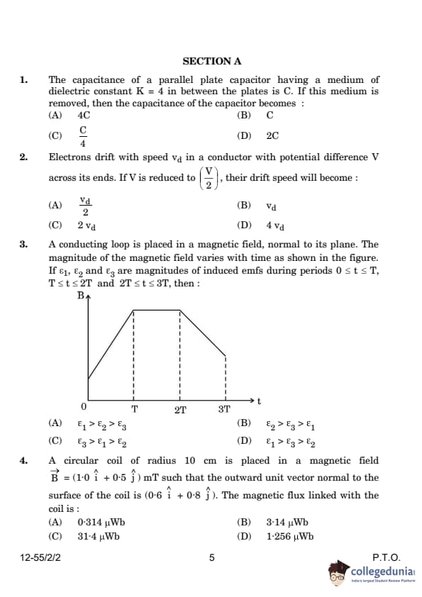
The capacitance of a parallel plate capacitor having a medium of dielectric constant \( K = 4 \) in between the plates is \( C \). If this medium is removed, then the capacitance of the capacitor becomes:
View Solution
The capacitance \( C \) of a parallel plate capacitor with dielectric constant \( K \) is given by: \[ C = \frac{K \varepsilon_0 A}{d}, \]
where \( A \) is the area of the plates, \( d \) is the separation between the plates, and \( \varepsilon_0 \) is the permittivity of free space.
When the dielectric medium with constant \( K = 4 \) is removed, the new capacitance \( C' \) is: \[ C' = \frac{\varepsilon_0 A}{d}. \]
Since the original capacitance with the dielectric was \( C = \frac{4 \varepsilon_0 A}{d} \), the ratio of the new capacitance to the original capacitance is: \[ \frac{C'}{C} = \frac{\frac{\varepsilon_0 A}{d}}{\frac{4 \varepsilon_0 A}{d}} = \frac{1}{4}. \]
\[ \frac{C'}{C} = \frac{1}{4}. \]
Thus, the new capacitance becomes \( \frac{C}{4} \). Quick Tip: For this problem, remember that removing the dielectric reduces the capacitance, as the dielectric constant \( K \) directly influences the capacitance value.
Electrons drift with speed \( v_d \) in a conductor with potential difference \( V \) across its ends. If \( V \) is reduced to \( \frac{V}{2} \), their drift speed will become:
View Solution
The drift velocity \( v_d \) is related to the potential difference \( V \) and the electric field \( E \) as: \[ v_d = \mu E, \]
where \( \mu \) is the mobility of the electrons. The electric field \( E \) is given by: \[ E = \frac{V}{L}, \]
where \( L \) is the length of the conductor. If the potential difference is reduced to \( \frac{V}{2} \), then the drift speed will become: \[ v_d' = \mu \cdot \frac{V/2}{L} = \frac{v_d}{2}. \] Quick Tip: For this problem, recall that the drift velocity is directly proportional to the electric field, which in turn is proportional to the potential difference.
A conducting loop is placed in a magnetic field, normal to its plane. The magnitude of the magnetic field varies with time as shown in the figure. If \( \varepsilon_1 \), \( \varepsilon_2 \), and \( \varepsilon_3 \) are magnitudes of induced emfs during periods \( 0 \leq t \leq T \), \( T \leq t \leq 2T \), and \( 2T \leq t \leq 3T \), then:

View Solution
The induced emf \( \varepsilon \) is given by Faraday's law: \[ \varepsilon = -\frac{d\Phi_B}{dt}, \]
where \( \Phi_B \) is the magnetic flux. The rate of change of flux will be greatest when the change in the magnetic field is the fastest. From the graph, we can see that the rate of change of magnetic field is maximum in the interval \( 0 \leq t \leq T \), thus \( \varepsilon_1 > \varepsilon_3 > \varepsilon_2 \). Quick Tip: For this problem, focus on the rate of change of the magnetic field, which determines the magnitude of the induced emf.
A circular coil of radius 10 cm is placed in a magnetic field \( \vec{B} = (1.0 \hat{i} + 0.5 \hat{j}) \, mT \) such that the outward unit vector normal to the surface of the coil is \( (0.6 \hat{i} + 0.8 \hat{j}) \). The magnetic flux linked with the coil is:
View Solution
The magnetic flux \( \Phi_B \) is given by: \[ \Phi_B = B A \cos \theta, \]
where \( B \) is the magnetic field, \( A \) is the area of the coil, and \( \theta \) is the angle between the magnetic field and the normal to the coil.
The area \( A \) of the coil is: \[ A = \pi r^2 = \pi (0.1)^2 = 0.0314 \, m^2. \]
The angle \( \theta \) is the angle between the magnetic field and the normal vector, and can be calculated using the dot product: \[ \cos \theta = \frac{\vec{B} \cdot \hat{n}}{|\vec{B}|}, \]
where \( \vec{B} = 1.0 \hat{i} + 0.5 \hat{j} \) and \( \hat{n} = 0.6 \hat{i} + 0.8 \hat{j} \).
After calculating the dot product and magnitudes: \[ \vec{B} \cdot \hat{n} = 1.0 \times 0.6 + 0.5 \times 0.8 = 0.88, \] \[ |\vec{B}| = \sqrt{(1.0)^2 + (0.5)^2} = 1.118, \] \[ \cos \theta = \frac{0.88}{1.118} = 0.788. \]
Now, the magnetic flux is: \[ \Phi_B = (1.118 \times 10^{-3}) (0.0314) (0.788) = 31.4 \, \mu Wb. \] Quick Tip: For this problem, use the dot product to find the angle between the magnetic field and the normal vector to the coil, and then apply the formula for magnetic flux.
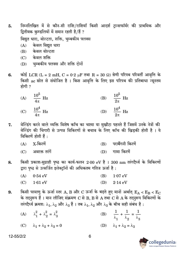
Which of the following quantity/quantities remains same in primary and secondary coils of an ideal transformer?
View Solution
In an ideal transformer, the power is conserved and hence the power in both primary and secondary coils remains the same. Additionally, the magnetic flux is also the same in both coils, as it is induced by the primary coil and links to the secondary coil.
\[ P_1 = P_2 \quad and \quad \Phi_1 = \Phi_2. \]
Thus, the correct answer is that both magnetic flux and power remain the same. Quick Tip: Remember that an ideal transformer assumes no energy losses, so both power and magnetic flux remain the same in the primary and secondary coils.
A series LCR circuit (L = 2 mH, C = 0.2 μF and R = 30 Ω) is connected to an ac source of variable frequency. The impedance of this circuit will be minimum at a frequency of:
View Solution
In a series LCR circuit, the impedance \( Z \) is given by: \[ Z = \sqrt{R^2 + (X_L - X_C)^2}, \]
where \( X_L = \omega L \) and \( X_C = \frac{1}{\omega C} \) are the inductive and capacitive reactances, respectively. The impedance is minimum when the inductive reactance equals the capacitive reactance, i.e., \( X_L = X_C \).
At this point, the resonant frequency \( f_0 \) is given by: \[ f_0 = \frac{1}{2\pi \sqrt{LC}}. \]
Substituting the values \( L = 2 \, mH = 2 \times 10^{-3} \, H \) and \( C = 0.2 \, \muF = 0.2 \times 10^{-6} \, F \): \[ f_0 = \frac{1}{2\pi \sqrt{(2 \times 10^{-3})(0.2 \times 10^{-6})}} = \frac{10^5}{4\pi} \, Hz. \]
Thus, the correct answer is \( \frac{10^5}{4\pi} \, Hz \). Quick Tip: To find the resonant frequency in a series LCR circuit, use the formula \( f_0 = \frac{1}{2\pi \sqrt{LC}} \) where \( L \) is inductance and \( C \) is capacitance.
Welders wear special glass goggles or face masks with glass windows to protect their eyes from radiations produced by welding arcs. These radiations are:
View Solution
Welding arcs produce intense ultraviolet (UV) radiation, which can be harmful to the eyes. Therefore, welders use special goggles or face masks to block this UV radiation and protect their eyes from damage. Quick Tip: Remember, UV radiation is highly energetic and harmful to the eyes, and it is a common source of eye injury in welding operations.
A photosensitive surface has a work function of 2.00 eV. The maximum kinetic energy of electrons ejected from this surface by radiation of wavelength 300 nm is:
View Solution
The maximum kinetic energy of ejected electrons is given by the photoelectric equation: \[ K_{max} = h\nu - \phi, \]
where \( h \) is Planck's constant, \( \nu \) is the frequency of the incident radiation, and \( \phi \) is the work function of the material. The frequency \( \nu \) is related to the wavelength \( \lambda \) by: \[ \nu = \frac{c}{\lambda}, \]
where \( c \) is the speed of light.
Given that \( \lambda = 300 \, nm = 300 \times 10^{-9} \, m \) and \( \phi = 2.00 \, eV \), we can calculate the energy of the incoming photons: \[ E_{photon} = \frac{hc}{\lambda} = \frac{6.626 \times 10^{-34} \times 3 \times 10^8}{300 \times 10^{-9}} = 4.14 \, eV. \]
Thus, the maximum kinetic energy is: \[ K_{max} = 4.14 - 2.00 = 2.14 \, eV. \] Quick Tip: Use the photoelectric equation and the relation between frequency and wavelength to calculate the maximum kinetic energy of ejected electrons.
Energy levels A, B, and C of an atom correspond to increasing values of energy i.e., \( E_A < E_B < E_C \). Let \( \lambda_1 \), \( \lambda_2 \), and \( \lambda_3 \) be the wavelengths of radiation corresponding to the transitions C to B, B to A, and C to A, respectively. The correct relation between \( \lambda_1 \), \( \lambda_2 \), and \( \lambda_3 \) is:
View Solution
The wavelengths of radiation corresponding to atomic transitions are related by the energy difference between the levels. According to the Rydberg formula for transitions: \[ \frac{1}{\lambda} = R \left( \frac{1}{n_1^2} - \frac{1}{n_2^2} \right), \]
where \( R \) is the Rydberg constant and \( n_1 \) and \( n_2 \) are the principal quantum numbers of the initial and final states, respectively. For the transitions described, the relation between the wavelengths is: \[ \frac{1}{\lambda_1} + \frac{1}{\lambda_2} = \frac{1}{\lambda_3}. \] Quick Tip: For transitions between energy levels, use the Rydberg formula to relate wavelengths to energy differences.
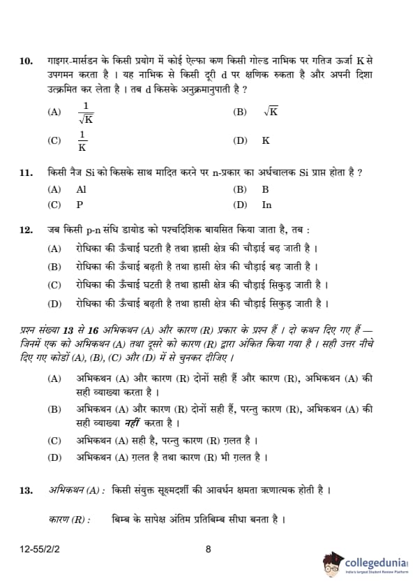
An alpha particle approaches a gold nucleus in Geiger-Marsden experiment with kinetic energy \( K \). It momentarily stops at a distance \( d \) from the nucleus and reverses its direction. Then \( d \) is proportional to:
View Solution
To determine the relationship between the distance \( d \) at which the alpha particle stops and its initial kinetic energy \( K \), we can use the principles of energy conservation and the Coulomb force.
1. Initial Kinetic Energy: The alpha particle has an initial kinetic energy \( K \).
2. Potential Energy at Distance \( d \): When the alpha particle stops, all its kinetic energy is converted into electrostatic potential energy. The potential energy \( U \) between the alpha particle (charge \( +2e \)) and the gold nucleus (charge \( +79e \)) at a distance \( d \) is given by:
\[ U = \frac{1}{4\pi\epsilon_0} \cdot \frac{(2e)(79e)}{d} \]
where \( \epsilon_0 \) is the permittivity of free space.
3. Energy Conservation: At the point where the alpha particle stops, its kinetic energy is zero, and its potential energy equals the initial kinetic energy:
\[ K = \frac{1}{4\pi\epsilon_0} \cdot \frac{158e^2}{d} \]
4. Solving for \( d \): Rearrange the equation to solve for \( d \):
\[ d = \frac{1}{4\pi\epsilon_0} \cdot \frac{158e^2}{K} \]
This shows that \( d \) is inversely proportional to \( K \):
\[ d \propto \frac{1}{K} \]
Therefore, the correct answer is:
\[ \boxed{C} \] Quick Tip: The distance at which a charged particle stops due to Coulomb's interaction is inversely proportional to the square root of its kinetic energy.
An n-type semiconducting Si is obtained by doping intrinsic Si with:
View Solution
An n-type semiconductor is formed by doping an intrinsic semiconductor with a group V element (such as phosphorus), which has five valence electrons. These extra electrons contribute to conductivity. In this case, phosphorus (P) is used for doping silicon to form an n-type semiconductor. Quick Tip: For n-type semiconductors, use elements from group V (like phosphorus) to provide extra electrons.
When a p-n junction diode is subjected to reverse biasing:
View Solution
In reverse biasing, the external voltage opposes the potential barrier of the p-n junction, which causes the depletion region to widen. This happens because the external voltage increases the barrier height, preventing current from flowing (except for a very small leakage current). Quick Tip: In reverse bias, the barrier height increases and the depletion region widens, leading to the prevention of current flow.
Assertion (A): The magnifying power of a compound microscope is negative.
Reason (R): The final image formed is erect with respect to the object.
View Solution
The assertion is correct because the magnifying power of a compound microscope is considered negative, as the final image is inverted relative to the object. However, the reason is incorrect because the final image formed is not erect but rather inverted with respect to the object. Therefore, the assertion is true, but the reason is false. Quick Tip: A compound microscope produces an inverted image, and its magnifying power is conventionally taken as negative.
Assertion (A): An electron and a proton enter with the same momentum \( \vec{p} \) in a magnetic field \( \vec{B} \) such that \( \vec{p} \perp \vec{B} \). Then both describe a circular path of the same radius.
Reason (R): The radius of the circular path described by the charged particle (charge \( q \), mass \( m \)) moving in the magnetic field \( \vec{B} \) is given by \( r = \frac{mv}{qB} \).
View Solution
The assertion is correct because when an electron and a proton enter the magnetic field with the same momentum, they experience the same force due to their charge and follow a circular path with the same radius. The radius of the circular path is given by the formula:
\[ r = \frac{p}{qB} \]
Since both have the same momentum and the formula depends on \( p \), the radii of their circular paths will be the same. Thus, both the assertion and the reason are true, and the reason correctly explains the assertion. Quick Tip: For a charged particle in a magnetic field, the radius of the circular motion depends on its momentum, charge, and magnetic field strength.
Assertion (A): Lenz's law is a consequence of the law of conservation of energy.
Reason (R): There is no power loss in an ideal inductor.
View Solution
Lenz’s law is a consequence of the conservation of energy, as it ensures that the induced current always flows in a direction that opposes the change in magnetic flux. The statement that there is no power loss in an ideal inductor is also true because an ideal inductor does not dissipate energy; instead, it stores energy in the magnetic field. However, this does not directly explain Lenz’s law, making option (2) the correct choice. Quick Tip: Lenz’s law follows the principle of conservation of energy, while an ideal inductor stores energy without dissipation, making both statements true but unrelated in explanation.
Assertion (A): Photoelectric current increases with an increase in intensity of incident radiation, for a given frequency of incident radiation and the accelerating potential.
Reason (R): Increase in the intensity of incident radiation results in an increase in the number of photoelectrons emitted per second and hence an increase in the photocurrent.
View Solution
When the intensity of incident radiation increases (for a constant frequency), the number of photons hitting the surface increases. This results in the emission of more photoelectrons per second, thereby increasing the photocurrent. This explanation aligns perfectly with the assertion. Quick Tip: The intensity of radiation affects the number of photoelectrons emitted, which in turn increases the photocurrent.
(a) "The electron drift speed is only a few mm/s for currents in the range of a few amperes for a given conductor." How then is current established almost the instant a circuit is closed? Explain.
(b) "V = IR is a statement of Ohm’s Law" is not true. Explain.
View Solution
(a) Establishment of Current in a Circuit:
Although electron drift speed is very slow, the electric field in a circuit propagates at nearly the speed of light in the conductor. This electric field is established almost instantly throughout the circuit when the switch is closed, causing a local electron drift at every point. Thus, current does not have to wait for electrons to travel from one end of the conductor to the other; instead, it is established instantaneously due to the propagation of the field.
(b) Understanding Ohm’s Law:
Ohm’s law states that the current \( I \) through a conductor is directly proportional to the voltage \( V \), provided the resistance \( R \) remains constant. Mathematically,
\[ V = IR \]
However, this equation itself does not define Ohm’s law; it merely expresses the relationship between \( V \), \( I \), and \( R \). The true assertion of Ohm’s law is that the plot of \( I \) versus \( V \) should be linear, implying that \( R \) is independent of \( V \). This equation can be applied to all conductors, whether they obey Ohm’s law or not. Quick Tip: The electric field propagates at nearly the speed of light in a conductor, enabling instant current establishment. Ohm’s law asserts a linear \( I \)-\( V \) relationship, whereas \( V = IR \) is a general equation applicable to all conductors.
A convex lens (\( n = 1.52 \)) has a focal length of 15.0 cm in air. Find its focal length when it is immersed in a liquid of refractive index 1.65. What will be the nature of the lens?
View Solution
Lens Maker's Formula
Let fa be the focal length of the convex lens in air and fl be the focal length of the convex lens in liquid.
Let ng be the refractive index of the lens material, na be the refractive index of air, and nl be the refractive index of the liquid.
Let R1 and R2 be the radii of curvature of the lens surfaces.
The lens maker's formula for a lens in air is given by:
1 / fa = (ng / na - 1) * (1 / R1 - 1 / R2)
The lens maker's formula for a lens in liquid is given by:
1 / fl = (ng / nl - 1) * (1 / R1 - 1 / R2)
We are given that ng = 1.52, na = 1, and nl = 1.65.
Dividing the second equation by the first equation, we get:
fl / fa = ( (ng / na) - 1 ) / ( (ng / nl) - 1 )
Substitute the values:
fl / fa = ( (1.52 / 1) - 1 ) / ( (1.52 / 1.65) - 1 )
We calculate this step by step:
        fl / fa = (1.52 - 1) / ((1.52 - 1.65) / 1.65)
        fl / fa = 0.52 / (-0.13 / 1.65)
        fl / fa = (0.52 * 1.65) / -0.13
        fl / fa = 0.858 / -0.13
        fl / fa = -6.6
Thus, fl = -6.6 fa.
Given that fa = 15 cm, we have:
fl = -6.6 * 15 = -99 cm
Since fl is negative, the convex lens in the liquid behaves as a diverging lens, or a concave lens.
Final Answer:
The final answer is -99 cm
Two waves, each of amplitude \( a \) and frequency \( \omega \) emanating from two coherent sources of light superpose at a point. If the phase difference between the two waves is \( \phi \), obtain an expression for the resultant intensity at that point.
View Solution
Let the equations of the two waves be: \[ x_1 = a \cos(\omega t), \] \[ x_2 = a \cos(\omega t + \phi), \]
where \( a \) is the amplitude, \( \omega \) is the frequency, and \( \phi \) is the phase difference.
The resultant displacement \( x \) is: \[ x = x_1 + x_2 = a \cos(\omega t) + a \cos(\omega t + \phi) = a ( \cos(\omega t) + \cos(\omega t + \phi) ). \]
Using the trigonometric identity: \[ \cos A + \cos B = 2 \cos\left(\frac{A+B}{2}\right) \cos\left(\frac{A-B}{2}\right), \]
we get: \[ x = 2a \cos\left(\frac{\phi}{2}\right) \cos\left(\omega t + \frac{\phi}{2}\right). \]
The intensity \( I \) is proportional to the square of the amplitude: \[ I = K (Amplitude)^2 = K \left(2a \cos\left(\frac{\phi}{2}\right)\right)^2 = 4K a^2 \cos^2\left(\frac{\phi}{2}\right). \]
Let \( I_0 = Ka^2 \) be the intensity of each incident wave. Thus, the resultant intensity is: \[ I = 4I_0 \cos^2\left(\frac{\phi}{2}\right). \] Quick Tip: The intensity of two superimposed waves depends on the square of the cosine of half the phase difference.
What is the effect on the interference pattern in Young's double-slit experiment when (i) the source slit is moved closer to the plane of the slits, and (ii) the separation between the two slits is increased? Justify your answers.
View Solution
(i) As the source slit is moved closer to the plane of the slits, the sharpness of the interference pattern decreases. This happens because the light from different parts of the source overlaps and the fringes begin to blur, eventually disappearing if the slit is moved too close. The fringe sharpness is affected by the ratio \( \frac{s}{d} \), where \( s \) is the distance between the source and the slits, and \( d \) is the separation between the slits. If \( s \) decreases, the sharpness of the interference pattern decreases.
(ii) As the separation between the two slits increases, the fringe spacing \( \beta \) decreases. The fringe spacing is given by: \[ \beta = \frac{\lambda D}{d}, \]
where \( \lambda \) is the wavelength of light, \( D \) is the distance from the slits to the screen, and \( d \) is the slit separation. As \( d \) increases, \( \beta \) decreases, and the fringes become closer together. Quick Tip: The sharpness of interference fringes depends on the relative distances between the source, slits, and screen. Adjusting these distances changes the fringe spacing.
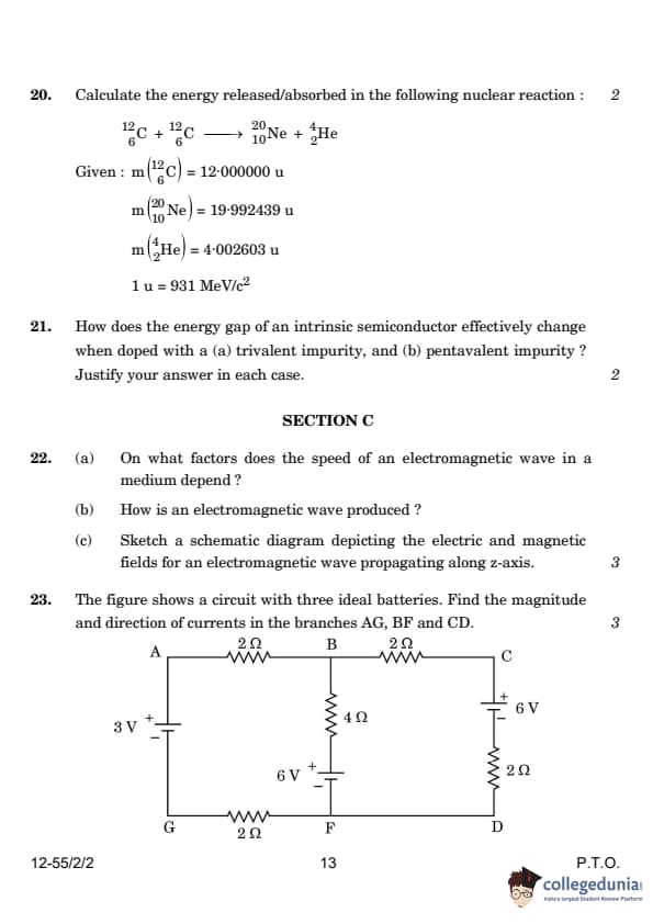
Calculate the energy released/absorbed in the following nuclear reaction: \[ ^{12}_6C + ^{12}_6C \rightarrow ^{20}_{10}Ne + ^4_2He \]
Given: \[ m(^{12}_6C) = 12.000000 \, u, \, m(^{20}_{10}Ne) = 19.992439 \, u, \, m(^{4}_2He) = 4.002603 \, u, \, 1 \, u = 931 \, MeV/c^2 \]
View Solution
The energy released or absorbed is given by the mass defect, which is calculated as: \[ \Delta m = (2 \times 12.000000 - 19.992439 - 4.002603) = 0.004958 \, u. \]
Now, the energy released is: \[ E = \Delta m \times 931 \, MeV/c^2 = 0.004958 \times 931 = 4.62 \, MeV. \] Quick Tip: When calculating energy released in nuclear reactions, use the mass defect and convert it into energy using \( E = \Delta m \times 931 \, MeV/c^2 \).
How does the energy gap of an intrinsic semiconductor effectively change when doped with a (a) trivalent impurity, and (b) pentavalent impurity? Justify your answer in each case.
View Solution
(i) Trivalent impurity: When a semiconductor is doped with a trivalent impurity (e.g., boron), it creates an acceptor energy level just above the valence band. This reduces the effective energy gap because electrons from the valence band can easily jump to the acceptor level, facilitating conduction.
(ii) Pentavalent impurity: When a semiconductor is doped with a pentavalent impurity (e.g., phosphorus), it creates a donor energy level just below the conduction band. This also reduces the effective energy gap since electrons from the donor level can easily move into the conduction band, making the material more conductive. Quick Tip: Doping with trivalent impurities creates acceptor levels above the valence band, while doping with pentavalent impurities creates donor levels below the conduction band, both reducing the energy gap.
(a) On what factors does the speed of an electromagnetic wave in a medium depend?
(b) How is an electromagnetic wave produced?
(c) Sketch a schematic diagram depicting the electric and magnetic fields for an electromagnetic wave propagating along the z-axis.
View Solution
(a) The speed \( v \) of an electromagnetic wave in a medium depends on:
- The permittivity \( \epsilon \) of the medium.
- The magnetic permeability \( \mu \) of the medium.
The speed of EM waves is given by: \[ v = \frac{1}{\sqrt{\mu \epsilon}}. \]
(b) Electromagnetic waves are produced by oscillating or accelerated charges, such as electrons in an antenna. These oscillating charges generate both electric and magnetic fields that propagate through space as an electromagnetic wave.
(c) The electric and magnetic fields for an electromagnetic wave propagating along the z-axis are perpendicular to each other and the direction of propagation. The electric field oscillates along the x-axis and the magnetic field along the y-axis, as shown in the diagram:

\[ Electric Field (E) \quad and \quad Magnetic Field (B) \quad in the direction of propagation (z-axis). \] Quick Tip: The speed of electromagnetic waves in a medium depends on the permittivity and permeability of the medium.
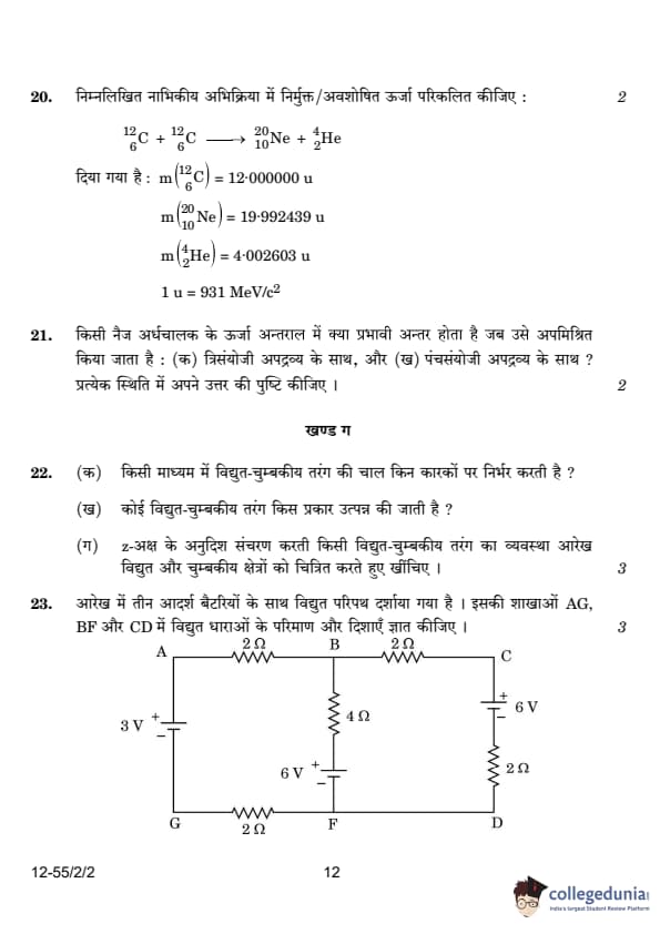
The figure shows a circuit with three ideal batteries. Find the magnitude and direction of currents in the branches AG, BF and CD.

View Solution
By applying Kirchhoff’s laws to the circuit, we can determine the currents in the different branches.
First, we use Kirchhoff’s current law at point B: \[ I_1 + I_2 = I_3 \]
Next, applying Kirchhoff’s loop rule for the closed loop AGFBA: \[ 3 + 2I_3 - 6 + 4I_2 + 2I_3 = 0 \]
Simplifying: \[ I_2 + I_3 = \frac{3}{4} \]
We substitute this in another equation based on another loop, BFDCB: \[ -4I_2 + 6 + 2I_1 - 6 + 2I_1 = 0 \]
Which simplifies to: \[ I_2 = I_1 \]
By solving the equations, we find: \[ I_1 = \frac{1}{4} \, A, \, I_2 = \frac{1}{4} \, A, \, I_3 = \frac{1}{2} \, A. \] Quick Tip: Kirchhoff’s laws are helpful for analyzing circuits with multiple batteries and resistors to determine currents and voltages.
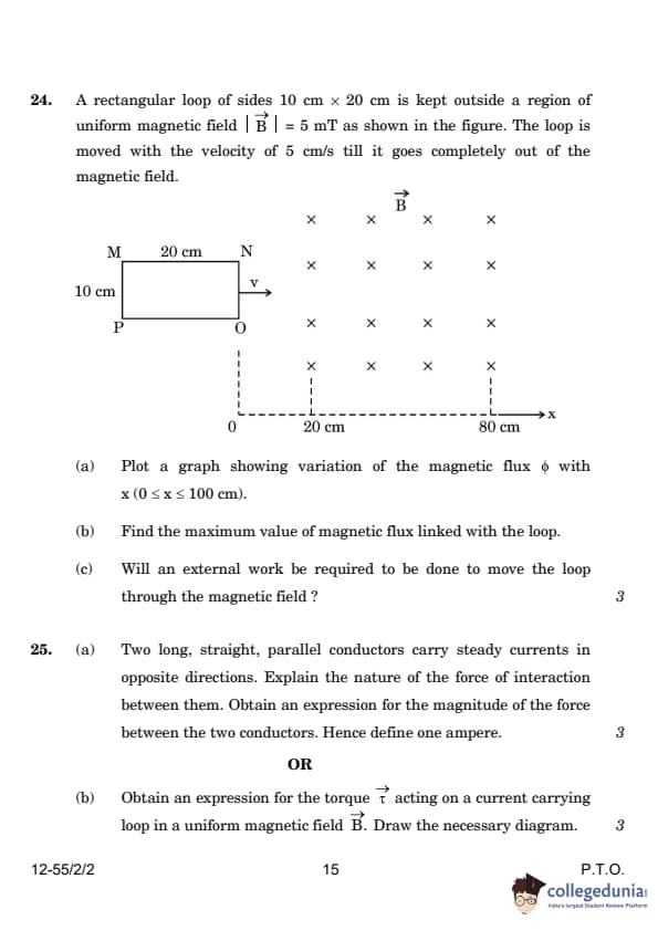
A rectangular loop of sides 10 cm \( \times \) 20 cm is kept outside a region of uniform magnetic field \( \vec{B} = 5 \, mT \) as shown in the figure. The loop is moved with a velocity of 5 cm/s till it goes completely out of the magnetic field.
[(a)] Plot a graph showing variation of the magnetic flux \( \phi \) with \( x \) (0 \( \leq x \leq \) 100 cm).
[(b)] Find the maximum value of magnetic flux linked with the loop.
[(c)] Will an external work be required to be done to move the loop through the magnetic field?
View Solution
(a) The magnetic flux \( \phi \) is the product of the magnetic field \( B \) and the area \( A \) of the loop. As the loop moves through the magnetic field, the area linked with the magnetic field increases. Therefore, the flux increases as the loop enters the field and decreases as it leaves the field. This results in a trapezoidal graph as shown.

(b) The maximum flux is when the loop is fully inside the magnetic field, so: \[ \phi = B \times A = (5 \times 10^{-3}) \times (20 \times 10^{-2}) \times (10 \times 10^{-2}) = 10^{-4} \, Wb. \]
(c) Yes, external work is required because the motion of the loop through the magnetic field induces a change in flux, and according to Faraday's law, this induces an emf. To keep the current constant, external work must be done. Quick Tip: Remember, the magnetic flux linked with the loop is the product of the magnetic field strength and the area of the loop that intersects the magnetic field. When the loop moves through the field, the area changes, and so does the flux.
Two long, straight, parallel conductors carry steady currents in opposite directions. Explain the nature of the force of interaction between them. Obtain an expression for the magnitude of the force between the two conductors. Hence define one ampere.
View Solution
The force between two parallel conductors carrying currents is due to the magnetic field produced by one conductor acting on the other. The force is repulsive if the currents are in opposite directions and attractive if the currents are in the same direction.
The magnitude of the force per unit length between two conductors is given by Ampère's force law: \[ F = \frac{\mu_0 I_1 I_2}{2 \pi d}, \]
where:
- \( I_1 \) and \( I_2 \) are the currents in the two conductors,
- \( d \) is the distance between them,
- \( \mu_0 \) is the permeability of free space.
One ampere is defined as the current that, when flowing through two parallel conductors one meter apart, produces a force of \( 2 \times 10^{-7} \, N/m \) on each conductor. Quick Tip: The force between two conductors depends on the current in each conductor and the distance between them.
Obtain an expression for the torque \( \tau \) acting on a current-carrying loop in a uniform magnetic field \( \vec{B} \). Draw the necessary diagram.
View Solution
The torque on a current loop in a magnetic field is given by the expression: \[ \tau = I A B \sin \theta, \]
where:
\( I \) is the current in the loop,
\( A \) is the area of the loop,
\( B \) is the magnetic field strength,
\( \theta \) is the angle between the normal to the loop and the magnetic field.

The forces on arms BC and DA are equal and opposite and cancel each other out, while the forces on arms AB and CD form a couple, leading to a torque.
\[ \tau = I A B \sin \theta. \] Quick Tip: The torque on a current loop in a magnetic field depends on the current, area of the loop, and the angle between the magnetic field and the loop's normal.
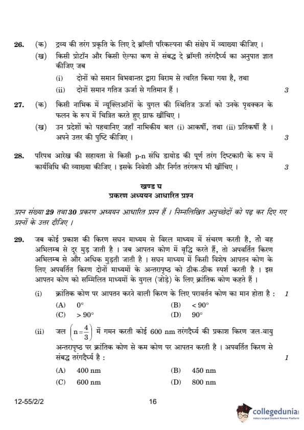
26. (a) Briefly explain de Broglie hypothesis for wave nature of matter.
View Solution
The de Broglie hypothesis states that particles of matter, such as electrons, can exhibit wave-like properties under suitable conditions. The wavelength \( \lambda \) associated with a particle of momentum \( p \) is given by: \[ \lambda = \frac{h}{p} = \frac{h}{mv}, \] where \( h \) is Planck's constant, \( m \) is the mass of the particle, and \( v \) is its velocity. Thus, all matter exhibits wave-like behavior, and the wavelength is inversely proportional to the momentum. Quick Tip: In a full-wave rectifier, both half-cycles of the input AC are used to produce a unidirectional output. The use of two diodes ensures the current flows in the same direction during both halves of the input waveform.
Find the ratio of de Broglie wavelength associated with a proton and an alpha particle when both are
[(i)] accelerated from rest through the same potential difference,
[(ii)] moving with the same kinetic energy.
View Solution
(i) When a proton and an alpha particle are accelerated through the same potential difference, the de Broglie wavelength is inversely proportional to the square root of the particle’s mass.
The wavelength λp associated with a proton and λα associated with an alpha particle is given by:
λp = h / &sqrt{2mpeV} and λα = h / &sqrt{2mαeV}
We are given:
&frac;λp⁄λα = &frac;&sqrt{2 * 4mp * 2e * V}}{&sqrt{2 * mp * e * V}}
Now, simplifying the expression:
&sqrt{2 * 4 * mp * 2 * e * V} = &sqrt{16 * mp * e * V} = 4&sqrt{mp * e * V}
&sqrt{2 * mp * e * V} = &sqrt{2} * &sqrt{mp * e * V}
The fraction becomes:
&frac;λp⁄λα = &frac{4&sqrt{mpeV}}{&sqrt{2}&sqrt{mpeV}}
Canceling out the common term &sqrt{mpeV}, we get:
&frac;λp⁄λα = &frac{4}{&sqrt{2}}
To rationalize the denominator, multiply both numerator and denominator by &sqrt{2}:
&frac{4}{&sqrt{2}} * &frac{&sqrt{2}}{&sqrt{2}} = &frac{4&sqrt{2}}{2}
Finally, simplifying the fraction:
&frac;λp⁄λα = 2&sqrt{2}
Thus, the simplified expression is 2&sqrt{2}.
(ii) When both particles move with the same kinetic energy, the de Broglie wavelength is inversely proportional to the square root of the mass of the particle.
The wavelength λp associated with a proton and λα associated with an alpha particle is given by:
λp = h / &sqrt{2mpK} and λα = h / &sqrt{2mαK}
We are given:
&frac;λp⁄λα = &frac;&sqrt{2 * 4mp * K}}{&sqrt{2 * mp * K}}
Now, simplifying the expression:
&frac;λp⁄λα = &frac;&sqrt{8mpK}}{&sqrt{2mpK}}
Since K and mp are positive, we can take them out of the square root:
&frac;λp⁄λα = &frac;&sqrt{8} * &sqrt{mpK}}{&sqrt{2} * &sqrt{mpK}}
The terms &sqrt{mpK} cancel out:
&frac;λp⁄λα = &frac;&sqrt{8}}{&sqrt{2}}
Since &sqrt{8} = &sqrt{4 * 2} = 2&sqrt{2}, we have:
&frac;λp⁄λα = &frac{2&sqrt{2}}{&sqrt{2}}
Finally, the &sqrt{2} terms cancel out, leaving:
&frac;λp⁄λα = 2
Thus, the simplified ratio of wavelengths is 2.
Final Answer:
The final answer is 2.
Quick Tip
Remember that the wavelength is inversely proportional to the momentum, which depends on both the mass and velocity (or kinetic energy) of the particle.
(a) Plot a graph depicting potential energy of a pair of nucleons in a nucleus as a function of their separation.
View Solution
The graph depicting potential energy of nucleons is shown below. As the nucleons approach each other, the potential energy becomes increasingly negative due to the attractive nuclear force. At some separation, the potential energy reaches a minimum, beyond which it increases due to the repulsive force.

Identify the regions where the nuclear force is (i) attractive, and (ii) repulsive. Justify your answer.
View Solution
(i) The nuclear force is attractive in the region where the potential energy is negative (before the potential reaches its minimum), as it pulls the nucleons together.
(ii) The nuclear force is repulsive in the region where the potential energy becomes positive (after the minimum), as it pushes the nucleons apart. Quick Tip: The nuclear force is attractive at larger separations and becomes repulsive at very small separations when the nucleons are extremely close to each other.
With the help of a circuit diagram, explain the working of a p-n junction diode as a full-wave rectifier. Draw its input and output waveforms.
View Solution
A full-wave rectifier using a p-n junction diode works by allowing current to flow in one direction during both half-cycles of the AC input. The circuit consists of two diodes, D1 and D2, arranged in a bridge configuration. When the input voltage at A with respect to the center tap is positive, the voltage at B becomes negative. Diode D1 is forward biased and conducts while diode D2 is reverse biased. During the negative half cycle, diode D1 is reverse biased, and diode D2 conducts, providing current in the same direction. 
% Input and output waveforms:
Quick Tip: In a full-wave rectifier, both half-cycles of the input AC are used to produce a unidirectional output. The use of two diodes ensures the current flows in the same direction during both halves of the input waveform.
When a ray of light propagates from a denser medium to a rarer medium, it bends away from the normal. When the incident angle is increased, the refracted ray deviates more from the normal. For a particular angle of incidence in the denser medium, the refracted ray just grazes the interface of the two surfaces. This angle of incidence is called the critical angle for the pair of media involved.
(i) For a ray incident at the critical angle, the angle of reflection is:
View Solution
The angle of incidence at the critical angle is the angle at which the refracted ray grazes the interface, i.e., it refracts along the boundary. At this point, the angle of refraction is \(90^\circ\), so by the law of reflection, the angle of reflection must also be \(90^\circ\).
Thus, the correct answer is:
\[
\boxed{\text{(D) } 90^\circ}.
\]
A ray of light of wavelength 600 nm is incident in water (\( n = \frac{4}{3} \)) on the water-air interface at an angle less than the critical angle. The wavelength associated with the refracted ray is:
View Solution
When light passes from one medium to another, the wavelength of the light changes. The relationship between the wavelengths in the two media is given by:
\[
\lambda_2 = \lambda_1 \frac{v_2}{v_1} = \lambda_1 \frac{n_1}{n_2},
\]
where \( \lambda_1 \) is the wavelength in the first medium (water), and \( \lambda_2 \) is the wavelength in the second medium (air).
Given:
\( \lambda_1 = 600 \, \text{nm} \),
\( n_1 = \frac{4}{3} \) (water),
\( n_2 = 1 \) (air).
Thus:
\[
\lambda_2 = 600 \times \frac{4}{3} = 800 \, \text{nm}.
\]
Thus, the correct answer is:
\[
\boxed{\text{(D) } 800 \, \text{nm}}.
\]
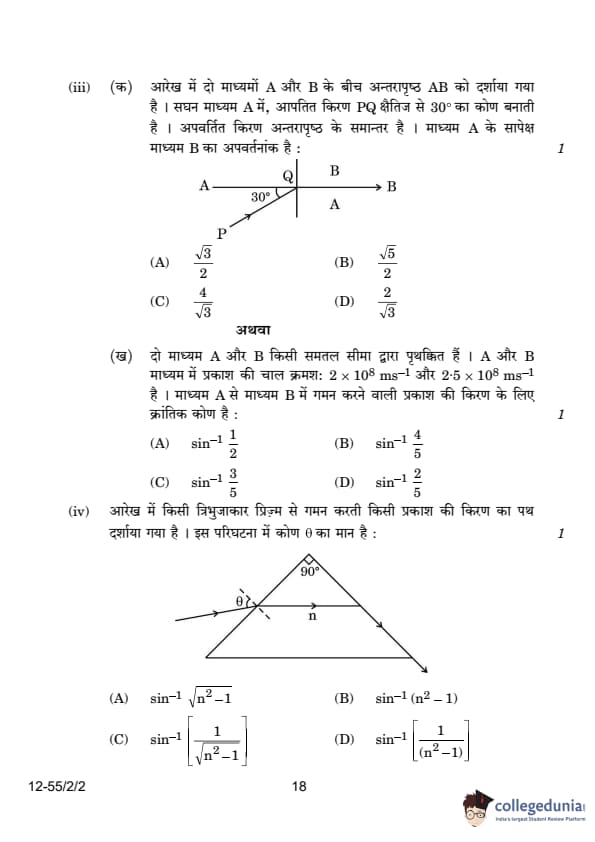
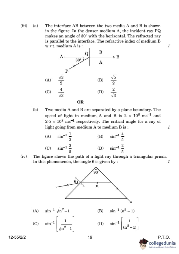
The interface AB between the two media A and B is shown in the figure. In the denser medium A, the incident ray PQ makes an angle of \( 30^\circ \) with the horizontal. The refracted ray is parallel to the interface. The refractive index of medium B with respect to medium A is:

View Solution
given
1. Medium A is denser than medium B.
2. The incident ray PQ in medium A makes an angle of \( 30^\circ \) with the horizontal.
3. The refracted ray in medium B is parallel to the interface AB.
4. We need to find the refractive index of medium B with respect to medium A (\( \mu_{BA} \)).
Step 1: Understand the geometry and angles
The incident ray PQ makes an angle of \( 30^\circ \) with the horizontal. This means the angle of incidence (\( i \)) with respect to the normal is:
\[
i = 90^\circ - 30^\circ = 60^\circ
\]
The refracted ray is parallel to the interface AB. This means the angle of refraction (\( r \)) is \( 90^\circ \) (since the refracted ray is parallel to the interface).
Step 2: Apply Snell's Law
Snell's Law states:
\[
\mu_A \sin i = \mu_B \sin r
\]
where:
\( \mu_A \) = refractive index of medium A,
\( \mu_B \) = refractive index of medium B,
\( i \) = angle of incidence,
\( r \) = angle of refraction.
From the problem:
\( i = 60^\circ \),
\( r = 90^\circ \).
Substitute these values into Snell's Law:
\[
\mu_A \sin 60^\circ = \mu_B \sin 90^\circ
\]
We know:
\( \sin 60^\circ = \frac{\sqrt{3}}{2} \),
\( \sin 90^\circ = 1 \).
So:
\[
\mu_A \cdot \frac{\sqrt{3}}{2} = \mu_B \cdot 1
\]
Step 3: Find the refractive index of medium B with respect to medium A
The refractive index of medium B with respect to medium A is defined as:
\[
\mu_{BA} = \frac{\mu_B}{\mu_A}
\]
From the equation in Step 2:
\[
\mu_B = \mu_A \cdot \frac{\sqrt{3}}{2}
\]
Divide both sides by \( \mu_A \):
\[
\mu_{BA} = \frac{\mu_B}{\mu_A} = \frac{\sqrt{3}}{2}
\]
The refractive index of medium B with respect to medium A is:
\[
\boxed{\frac{\sqrt{3}}{2}}
\]
Thus, the correct option is (1).
Two media A and B are separated by a plane boundary. The speed of light in medium A and B is \( 2 \times 10^8 \, ms^{-1} \) and \( 2.5 \times 10^8 \, ms^{-1} \), respectively. The critical angle for a ray of light going from medium A to medium B is:

View Solution
Using Snell’s law for the critical angle \( \theta_c \): \[ n_A \sin \theta_c = n_B \sin 90^\circ = 1. \]
Hence, \[ \sin \theta_c = \frac{v_A}{v_B} = \frac{2 \times 10^8}{2.5 \times 10^8} = \frac{4}{5}. \]
Thus, the critical angle is: \[ \theta_c = \sin^{-1} \left( \frac{4}{5} \right). \]
Thus, the correct answer is: \[ \boxed{(B) \sin^{-1} \frac{4}{5}}. \]
The figure shows the path of a light ray through a triangular prism. In this phenomenon, the angle \( \theta \) is given by:
View Solution
For the given triangular prism, the angle \( \theta \) is related to the refractive index of the material of the prism. Using Snell's law and geometrical principles, the relationship is given by: \[ \boxed{(A) \sin^{-1} \sqrt{n^2 - 1}}. \] Quick Tip: In cases involving refraction and critical angles, remember to use Snell's Law, \( n_1 \sin \theta_1 = n_2 \sin \theta_2 \), to calculate refractive indices or angles accurately.
When the terminals of a cell are connected to a conductor of resistance \( R \), an electric current flows through the circuit. The electrolyte of the cell also offers some resistance in the path of the current, like the conductor. This resistance offered by the electrolyte is called internal resistance of the cell \( r \). It depends upon the nature of the electrolyte, the area of the electrodes immersed in the electrolyte, and the temperature. Due to internal resistance, a part of the energy supplied by the cell is wasted in the form of heat.
When no current is drawn from the cell, the potential difference between the two electrodes is known as emf of the cell \( \varepsilon \). With a current drawn from the cell, the potential difference between the two electrodes is termed as terminal potential difference \( V \).
(i) Choose the incorrect statement:
(A) The potential difference \( V \) between the two terminals of a cell in a closed circuit is always less than its emf \( \varepsilon \), during discharge of the cell.
(B) The internal resistance of a cell decreases with the decrease in temperature of the electrolyte.
(C) When current is drawn from the cell then \( V = I r \).
(D) The graph between potential difference between the two terminals of the cell \( V \) and the current \( I \) through it is a straight line with a negative slope.
View Solution
The incorrect statement is: (B) The internal resistance of a cell decreases with the decrease in temperature of the electrolyte. The internal resistance actually increases as the temperature of the electrolyte decreases. Lower temperatures hinder the movement of ions, which increases the resistance.
Two cells of emf 2.0 V and 6.0 V and internal resistances 0.1 and 0.4 respectively, are connected in parallel. The equivalent emf of the combination will be:
View Solution
For cells connected in parallel, the equivalent emf \( \varepsilon_{eq} \) is given by the formula: \[ \varepsilon_{eq} = \frac{r_1 \varepsilon_2 + r_2 \varepsilon_1}{r_1 + r_2}, \]
where \( \varepsilon_1 \) and \( \varepsilon_2 \) are the emf values of the two cells, and \( r_1 \) and \( r_2 \) are their respective internal resistances.
Substituting the given values: \[ \varepsilon_{eq} = \frac{0.1 \times 6.0 + 0.4 \times 2.0}{0.1 + 0.4} = \frac{0.6 + 0.8}{0.5} = 2.8 \, V. \]
Thus, the correct answer is: \[ \boxed{(B)} \quad 2.8 \, V. \] Quick Tip: When cells are connected in parallel, the equivalent emf depends on the internal resistances and emfs of the cells.
Dipped in the solution, the electrode exchanges charges with the electrolyte. The positive electrode develops a potential \( V_+ \) (\( V_+ > 0 \)), and the negative electrode develops a potential \(-V_-\) (\( V_- \geq 0 \)), relative to the electrolyte adjacent to it. When no current is drawn from the cell, then:
View Solution
The electromotive force (emf) of the cell is given by the sum of the potential differences between the positive and negative electrodes relative to the electrolyte. Since both \( V_+ \) and \( V_- \) are positive, their sum is also positive, making option (A) correct.
Quick Tip: The internal resistance of a cell affects the terminal voltage when a current is drawn. For parallel-connected identical cells, the total emf remains the same, but the internal resistance is reduced.
Five identical cells, each of emf 2 V and internal resistance 0.1 \( \Omega \), are connected in parallel. This combination in turn is connected to an external resistor of 9.98 \( \Omega \). The current flowing through the resistor is:
View Solution
Since the five identical cells are connected in parallel, the total emf of the combination remains 2V. The equivalent internal resistance of the parallel combination is:
Equation 1: req = r / n = 0.1 / 5 = 0.02 Ω
Total resistance in the circuit:
Equation 2: Rtotal = Rext + req = 9.98 + 0.02 = 10 Ω
Current in the circuit:
Equation 3: I = E / Rtotal = 2 / 10 = 0.2 A
Potential difference across a cell in the open circuit is 6 V. It becomes 4 V when a current of 2 A is drawn from it. The internal resistance of the cell is:
View Solution
The internal resistance \( r \) is given by:
\[ V = E - Ir \]
Substituting the given values:
\[ 4 = 6 - (2 \times r) \]
\[ 2r = 2 \]
\[ r = 1.0 \Omega \] Quick Tip: The internal resistance of a cell affects the terminal voltage when a current is drawn. For parallel-connected identical cells, the total emf remains the same, but the internal resistance is reduced.
(i) Give any two differences between the interference pattern obtained in Young's double-slit experiment and a diffraction pattern due to a single slit.
View Solution
The interference pattern obtained in Young's double-slit experiment has equally spaced bright bands, with constant intensity. In contrast, the diffraction pattern from a single slit shows maxima and minima, where the maxima become weaker on either side of the central maximum.
| Interference | Diffraction |
|---|---|
| 1. Bands are equally spaced. | 1. Bands are not equally spaced. |
| 2. Intensity of bright bands is the same. | 2. Intensity of maxima decreases on either side of the central maxima. |
| 3. First maxima is at an angle λ/a. | 3. First minima is at an angle λ/a. |
Draw an intensity distribution graph in case of a double-slit interference pattern.
View Solution

The graph depicts maxima and minima as a result of constructive and destructive interference, with maxima occurring at integer multiples of \( \lambda \) and minima at odd multiples of \( \lambda/2 \). Quick Tip: The intensity distribution for a double-slit interference pattern follows a sinusoidal curve, with alternating bright and dark bands representing constructive and destructive interference.
In Young's double-slit experiment using monochromatic light of wavelength \( \lambda \), the intensity of light at a point on the screen, where path difference is \( \lambda \), is \( K \) units. Find the intensity of light at a point on the screen where the path difference is \( \lambda / 6 \).
View Solution
We know that the intensity at a point in Young's double-slit experiment is given by: \[ I = I_0 \cos^2 \left( \frac{\pi \Delta}{\lambda} \right), \]
where \( I_0 \) is the maximum intensity and \( \Delta \) is the path difference.
For path difference \( \Delta = \lambda \), the intensity is \( K \). Thus, we have: \[ K = I_0 \cos^2 \left( \pi \right) = I_0. \]
Now, for the path difference \( \Delta = \lambda / 6 \), we calculate the intensity: \[ I = I_0 \cos^2 \left( \frac{\pi}{6} \right) = I_0 \times \left( \frac{\sqrt{3}}{2} \right)^2 = \frac{3}{4} I_0. \]
Since \( K = I_0 \), the intensity at a point where the path difference is \( \lambda / 6 \) is: \[ I = \frac{3}{4} K. \] Quick Tip: When the path difference is not an integer multiple of \( \lambda \), use the formula for intensity and calculate using the cosine squared function for accurate results.
(i) Draw a labelled ray diagram of a compound microscope showing image formation at least distance of distinct vision. Derive an expression for its magnifying power.
View Solution
The ray diagram for a compound microscope is as follows:

In a compound microscope, the objective lens forms a real, inverted, and diminished image at the focal plane of the eyepiece. The eyepiece acts as a magnifier to form a virtual, erect, and magnified image at the least distance of distinct vision. The magnifying power \( M \) of the compound microscope is given by the product of the magnifying powers of the objective lens \( M_o \) and the eyepiece lens \( M_e \): \[ M = M_o \times M_e. \] The magnifying power of the objective lens is given by: \[ M_o = \frac{v_o}{u_o}, \] where \( v_o \) is the image distance and \( u_o \) is the object distance for the objective lens. Since the image is formed at the focal length of the objective lens \( f_o \), we have: \[ v_o = f_o. \] For the eyepiece, the magnifying power is given by: \[ M_e = \frac{D}{f_e}, \] where \( D \) is the least distance of distinct vision and \( f_e \) is the focal length of the eyepiece. Thus, the total magnifying power is: \[ M = \frac{f_o}{u_o} \times \frac{D}{f_e}. \]
Quick Tip: For a compound microscope, the magnifying power is the product of the magnifying powers of the objective and the eyepiece. The objective magnifies the object, and the eyepiece further magnifies the image formed.
A telescope consists of two lenses of focal length 100 cm and 5 cm. Find the magnifying power when the final image is formed at infinity.
View Solution
In a telescope, the magnifying power \( M \) is given by the ratio of the focal lengths of the objective and the eyepiece: \[ M = \frac{f_o}{f_e}. \] Here, \( f_o = 100 \, \text{cm} \) and \( f_e = 5 \, \text{cm} \), so the magnifying power is: \[ M = \frac{100}{5} = 20. \] Thus, the magnifying power of the telescope is 20.
Quick Tip: The magnifying power of a telescope is simply the ratio of the focal length of the objective lens to the focal length of the eyepiece when the final image is formed at infinity.
Obtain an expression for the electric potential due to a small dipole of dipole moment \( \vec{p} \), at a point \( \vec{r} \) from its centre, for much larger distances compared to the size of the dipole.
View Solution
The electric potential due to a dipole is the sum of potentials due to the charges \( +q \) and \( -q \) separated by distance \( 2a \):
V = 1/(4πϵ₀) [q/r₁ - q/r₂]
Using the geometry of the dipole, we have:
r₁² = r² + a² - 2ar cosθ, r₂² = r² + a² + 2ar cosθ
For \( r \gg a \), using binomial expansion and retaining first-order terms:
1/r₁ ≈ 1/r [1 - (a cosθ)/r], 1/r₂ ≈ 1/r [1 + (a cosθ)/r]
Substituting these into the potential equation:
V = (q / 4πϵ₀) [2a cosθ / r²]
Since dipole moment \( p = 2qa \), we get:
V = p cosθ / 4πϵ₀ r²
Three point charges \( q \), \( 2q \) and \( nq \) are placed at the vertices of an equilateral triangle. If the potential energy of the system is zero, find the value of \( n \).
View Solution
Potential Energy of the System
The potential energy of the system is given by:
U = &frac;k;{q q2} / a + &frac;k;{q2 q3} / a + &frac;k;{q3 q} / a
Substituting the given values:
U = &frac;k;(q)(2q) / a + &frac;k;(2q)(nq) / a + &frac;k;(q)(nq) / a = 0
Simplifying:
&frac{2q2}{a} + &frac{2nq2}{a} + &frac{nq2}{a} = 0
Next, solving for n:
2 + 2n + n = 0 ⇒ 3n = -2
Finally:
n = -&frac;2;{3}
State Gauss's law in electrostatics. Apply this to obtain the electric field E at a point near a uniformly charged infinite plane sheet:
View Solution
Gauss's Law
Gauss’s Law states:
∮ &vec;E · d&vec;S = &frac;q;{ε0}
For a uniformly charged infinite sheet, the electric field is given by:
E = &frac;σ{2ε0}
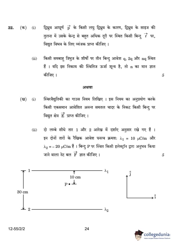
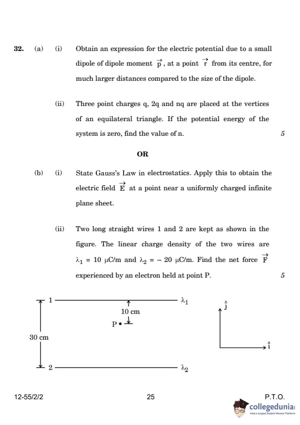
Two long straight wires 1 and 2 are kept as shown in the figure. The linear charge density of the two wires are \(\lambda\) 1 = 10 C/m and \(\lambda\)2 = -20 C/m. Find the net force F experienced by an electron held at point P:
View Solution
The electric field due to a long straight wire is given by:

\[ E = \frac{\lambda}{2\pi\epsilon_0 r} \]
For the two wires:
\[ E_1 = \frac{\lambda_1}{2\pi\epsilon_0 r_1}, \quad E_2 = \frac{\lambda_2}{2\pi\epsilon_0 r_2} \]
Substituting the given values:
\[ E_1 = \frac{10 \times 10^{-6}}{2\pi\epsilon_0 (10 \times 10^{-2})} (-\hat{j}) \]
\[ E_2 = \frac{20 \times 10^{-6}}{2\pi\epsilon_0 (20 \times 10^{-2})} (-\hat{j}) \]
Net electric field:
\[ E_{net} = \frac{10 \times 10^{-6}}{2\pi\epsilon_0} \left(\frac{1}{0.1} + \frac{2}{0.2} \right) (-\hat{j}) \]
\[ E_{net} = 3.6 \times 10^6 (-\hat{j}) N/C \]
Force on the electron:
\[ F_{net} = qE_{net} \]
\[ F_{net} = (-1.6 \times 10^{-19}) \times (3.6 \times 10^6) N \]
\[ F_{net} = 5.76 \times 10^{-13} N (\hat{j}) \] Quick Tip: The electric potential due to a dipole follows an inverse square law, whereas for a charged infinite plane, the electric field remains uniform and independent of distance.
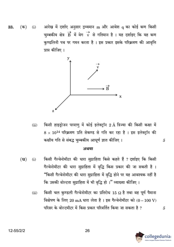
A particle of mass \( m \) and charge \( q \) is moving with a velocity \( \vec{v} \) in a magnetic field \( \vec{B} \) as shown in the figure. Show that it follows a helical path. Hence, obtain its frequency of revolution.

View Solution
The motion of a charged particle in a magnetic field can be analyzed into two components of velocity:
1. A component \( v_{\perp} \) perpendicular to the magnetic field, causing circular motion.
2. A component \( v_{\parallel} \) parallel to the magnetic field, causing linear motion along the direction of the field.
The total velocity \( v \) is the vector sum of these two components: \[ v_{\perp} = v \sin \theta, \quad v_{\parallel} = v \cos \theta. \]
The perpendicular component causes circular motion, and the parallel component causes linear motion along the magnetic field direction, resulting in a helical path.
The magnetic force provides the centripetal force for the circular motion, which gives the radius \( r \) of the circular path: \[ \frac{mv_{\perp}^2}{r} = q v_{\perp} B. \]
Solving for \( r \): \[ r = \frac{mv_{\perp}}{qB}. \]
The time period \( T \) for one complete revolution is the circumference of the circle divided by the velocity: \[ T = \frac{2\pi r}{v_{\perp}} = \frac{2\pi m}{qB}. \]
The frequency of revolution \( \nu \) is the reciprocal of the time period: \[ \nu = \frac{1}{T} = \frac{qB}{2\pi m}. \]
Thus, the particle follows a helical path with a frequency of revolution \( \nu = \frac{qB}{2\pi m} \).
Quick Tip: A charged particle moving in a magnetic field will follow a helical path due to the combination of circular motion caused by the perpendicular velocity component and linear motion caused by the parallel velocity component.
In a hydrogen atom, the electron moves in an orbit of radius \( 2 \, Å \) making \( 8 \times 10^{14} \) revolutions per second. Find the magnetic moment associated with the orbital motion of the electron.
View Solution
We are given the radius \( r = 2 \, Å = 2 \times 10^{-10} \, m \) and the frequency of revolution \( \nu = 8 \times 10^{14} \, rev/s \).
The magnetic moment \( m \) of a moving charge is given by: \[ m = I \cdot A, \]
where \( I \) is the current due to the motion of the electron, and \( A \) is the area of the circular orbit traced by the electron.
The current \( I \) is related to the charge and the frequency of revolution: \[ I = q \cdot \nu. \]
Substituting the known values for charge of the electron \( q = 1.6 \times 10^{-19} \, C \) and frequency \( \nu = 8 \times 10^{14} \, rev/s \): \[ I = 1.6 \times 10^{-19} \cdot 8 \times 10^{14} = 1.28 \times 10^{-4} \, A. \]
The area \( A \) of the circular orbit is: \[ A = \pi r^2 = \pi (2 \times 10^{-10})^2 = 1.26 \times 10^{-19} \, m^2. \]
Thus, the magnetic moment is: \[ m = I \cdot A = (1.28 \times 10^{-4}) \cdot (1.26 \times 10^{-19}) = 1.61 \times 10^{-23} \, Am^2. \]
The magnetic moment associated with the orbital motion of the electron is \( 1.61 \times 10^{-23} \, Am^2 \).
Quick Tip: The magnetic moment of a particle moving in a circular path is proportional to the current generated by the motion and the area enclosed by the path.
What is current sensitivity of a galvanometer? Show how the current sensitivity of a galvanometer may be increased. Increasing the current sensitivity of a galvanometer may not necessarily increase its voltage sensitivity. Explain.
View Solution
The current sensitivity of a galvanometer is defined as the deflection produced per unit current passing through it. It is given by the formula: \[ I_s = \frac{\theta}{I} = \frac{NBA}{K}, \]
where \( \theta \) is the angular deflection, \( I \) is the current, \( N \) is the number of turns of the coil, \( B \) is the magnetic field strength, \( A \) is the area of the coil, and \( K \) is the torsional constant.
The current sensitivity can be increased by:
Increasing the number of turns in the coil.
Increasing the area of the coil in the magnetic field.
Decreasing the torsional constant \( K \) (which means making the suspension more flexible).
Increasing the current sensitivity by changing the coil's properties may also affect the resistance of the galvanometer, which in turn can alter its voltage sensitivity. As the current sensitivity increases, the voltage sensitivity may decrease because the resistance increases, which can reduce the voltage required for full-scale deflection.
The current sensitivity is directly proportional to the number of turns and the area of the coil, but increasing the current sensitivity does not necessarily lead to an increase in voltage sensitivity. Voltage sensitivity is related to the resistance of the galvanometer, and increasing the number of turns to increase current sensitivity will also increase the resistance, thereby decreasing the voltage sensitivity. Quick Tip: The current sensitivity can be increased by increasing the number of turns, the area of the coil, or decreasing the torsional constant. However, increasing the current sensitivity may not always increase voltage sensitivity.
A moving coil galvanometer has a resistance of 15 Ω and takes 20 mA to produce full-scale deflection. How can this galvanometer be converted into a voltmeter of range 0 to 100 V?
View Solution
To convert the galvanometer into a voltmeter, we need to connect a series resistance \( R_s \) with the galvanometer. The value of \( R_s \) can be calculated using the following relation: \[ V = I_G (R + R_s), \]
where \( V \) is the full-scale deflection voltage (100 V), \( I_G \) is the current for full-scale deflection (20 mA), and \( R \) is the resistance of the galvanometer (15 Ω).
Rearranging to solve for \( R_s \): \[ R_s = \frac{V}{I_G} - R = \frac{100}{20 \times 10^{-3}} - 15 = 5000 - 15 = 4985 \, \Omega. \]
Thus, the required series resistance is 4985 Ω.
By connecting a 4985 Ω resistor in series with the galvanometer, it can be converted into a voltmeter with a full-scale range of 0 to 100 V. Quick Tip: To convert a galvanometer into a voltmeter, a high resistance is connected in series. The value of the resistance is calculated to achieve the desired voltage range for full-scale deflection.


Comments