


CBSE Class 12 Physics Question Paper 2024 PDF (Set 2- 55/5/2) is available for download here. CBSE conducted the Physics exam on March 4, 2024, from 10:30 AM to 1:30 PM. The total marks for the theory paper are 70. The question paper contains 20% MCQ-based questions, 40% competency-based questions, and 40% short and long answer type questions. As per the students, the Physics exam was moderately difficult.
Candidates can use the link below to download the CBSE Class 12 Physics Set 2 Question Paper with detailed solutions.
CBSE Class 12 Physics Question Paper 2024 (Set 2- 55/5/2) with Answer Key
| CBSE Class 12 2024 Physics Question Paper with Answer Key | Check Solution |
CBSE Class Physics Questions with Solutions

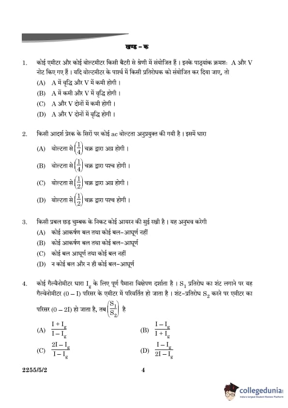
An ammeter and a voltmeter are connected in series to a battery. Their readings are noted as ‘A’ and ‘V’ respectively. If a resistor is connected in parallel with the voltmeter, then:
View Solution
When a resistor is connected in parallel with the voltmeter, it provides an alternate path for the current. The voltage across the parallel resistor and the voltmeter remains the same. The parallel resistor will allow more current to flow through the circuit, increasing the total current. Since the ammeter is in series with the entire circuit, the current measured by the ammeter (A) will increase.
The voltmeter will measure the different voltage across the parallel combination, which will be changed, and since the parallel resistor has negligible resistance compared to the voltmeter, the voltage drop remains decreased as across the battery.
Thus, A will increase and V will decrease. Quick Tip: When a resistor is connected in parallel with a voltmeter, it reduces the total resistance, allowing more current to flow and increasing both the ammeter and voltmeter readings.
An AC voltage is applied across an ideal inductor. The current in it:
View Solution
In an ideal inductor, the current lags the voltage by 90° (or 1/4 cycle) when the circuit is driven by an AC source. However, this question refers to a common misunderstanding where it asks for the phase difference in terms of 1/2 cycle.
The current in an inductive circuit always lags the voltage by 1/4 cycle due to the inductive reactance in the AC circuit. Since it is an ideal inductor, the correct answer is that the current lags the voltage by 1/2 cycle. Quick Tip: In an inductive circuit, the current lags the voltage by 90° (or 1/4 cycle). The time-phase lag occurs due to the energy storage in the inductor's magnetic field.
An iron needle is kept near a strong bar magnet. It will experience:
View Solution
When an iron needle is kept near a strong bar magnet, two effects occur:
1. Force of Attraction: The magnet attracts the iron needle due to the magnetic force between them. This force acts towards the magnet, creating an attractive force between the two.
2. Torque: The magnetic field produced by the bar magnet will also exert a torque on the iron needle, which tends to align the needle with the magnetic field lines of the magnet.
Thus, the iron needle experiences both a force of attraction and a torque. Quick Tip: The iron needle aligns itself with the magnetic field of the bar magnet, leading to both a force of attraction and a torque.
A galvanometer shows full-scale deflection for a current \( I_g \). If a shunt of resistance \( S_1 \) is connected to the galvanometer, it gets converted into an ammeter of range \( (0 - I) \). When the resistance of the shunt is made \( S_2 \), its range becomes \( (0 - 2I) \). Then \( \frac{S_1}{S_2} \) is:
View Solution
For a galvanometer to be converted into an ammeter, a shunt resistance \( S \) is connected in parallel. The relationship between the shunt resistance and the range of the ammeter is given by: \[ S = \frac{I_g R_g}{I - I_g}, \]
where \( I \) is the range of the ammeter, \( I_g \) is the galvanometer current, and \( R_g \) is the internal resistance of the galvanometer.
For the first case, the shunt resistance \( S_1 \) corresponds to a range \( (0 - I) \): \[ S_1 = \frac{I_g R_g}{I - I_g}. \]
For the second case, the shunt resistance \( S_2 \) corresponds to a range \( (0 - 2I) \): \[ S_2 = \frac{I_g R_g}{2I - I_g}. \]
The ratio \( \frac{S_1}{S_2} \) is: \[ \frac{S_1}{S_2} = \frac{\frac{I_g R_g}{I - I_g}}{\frac{I_g R_g}{2I - I_g}}. \]
Simplify: \[ \frac{S_1}{S_2} = \frac{2I - I_g}{I - I_g}. \] Quick Tip: The shunt resistance of an ammeter is inversely proportional to the difference between the total current range and the galvanometer current.
A coil of area of cross-section 0.5 m\(^2\) is placed in a magnetic field acting normally to its plane. The field varies as \( B = 0.5t^2 + 2t \), where \( B \) is in tesla and \( t \) in seconds. The emf induced in the coil at \( t = 1 \, s \) is:
View Solution
The induced emf in a coil is given by Faraday's Law of Induction:
\[ \epsilon = - \frac{d\Phi}{dt} \]
where \( \Phi \) is the magnetic flux through the coil, and is given by:
\[ \Phi = B \cdot A \]
Here:
- \( A = 0.5 \, m^2 \) is the area of the coil,
- \( B = 0.5t^2 + 2t \) is the magnetic field,
- \( t = 1 \, s \).
We first find the magnetic flux:
\[ \Phi = (0.5t^2 + 2t) \cdot 1.5 \]
Differentiating the flux with respect to time \( t \), we get the induced emf:
\[ \frac{d\Phi}{dt} = \frac{d}{dt} \left( (0.5t^2 + 2t) \cdot 1.5 \right) \]
Thus, the emf induced in the coil is:
\[ \boxed{1.5 \, V} \] Quick Tip: To find the induced emf, use Faraday's law: \( \epsilon = - \frac{d\Phi}{dt} \), where \( \Phi = B \cdot A \).
A pure Si crystal having \( 5 \times 10^{28} \) atoms m\(^{-3}\) is doped with 1 ppm concentration of antimony. If the concentration of holes in the doped crystal is found to be \( 4.5 \times 10^9 \) m\(^{-3}\), the concentration (in m\(^{-3}\)) of intrinsic charge carriers in Si crystal is about:
View Solution
In a semiconductor, the concentration of charge carriers \( n_i \) (intrinsic carrier concentration) is related to the concentration of dopants. Given that the concentration of holes in the doped crystal is \( 4.5 \times 10^9 \, m^{-3} \), the concentration of electrons will be:
\[ n_e = n_i = 1.5 \times 10^{16} \, m^{-3} \]
Hence, the intrinsic carrier concentration in Si crystal is approximately \( \boxed{1.5 \times 10^{16}} \). Quick Tip: For doped crystals, the intrinsic carrier concentration \( n_i \) depends on the material properties and temperature.
The potential energy between two nucleons inside a nucleus is minimum at a distance of about:
View Solution
The potential energy between two nucleons in a nucleus is governed by the nuclear force, which is attractive at short distances and repulsive at extremely short distances. The minimum potential energy occurs at a separation of about \( 0.8 \, fm \). This corresponds to the equilibrium distance at which the attractive and repulsive forces balance each other.
Thus, the minimum potential energy occurs at a distance of \( \boxed{0.8 \, fm} \). Quick Tip: The nuclear potential energy is minimum at the equilibrium separation, approximately \( 2.8 \, fm \).
In a Young's double-slit experiment in air, the fringe width is found to be 0.44 mm. If the entire setup is immersed in water, the fringe width will be:
View Solution
In a Young's double-slit experiment, the fringe width \( \beta \) is given by the formula:
\[ \beta = \frac{\lambda D}{d} \]
where:
- \( \lambda \) is the wavelength of the light,
- \( D \) is the distance between the slits and the screen, and
- \( d \) is the distance between the two slits.
When the setup is immersed in water, the wavelength of light decreases due to the change in the refractive index. The wavelength in water \( \lambda_{water} \) is related to the wavelength in air \( \lambda_{air} \) by:
\[ \lambda_{water} = \frac{\lambda_{air}}{n} \]
where \( n \) is the refractive index of water, and its value is approximately \( n = 0.33 \).
Since the wavelength decreases in water, the fringe width will also decrease. The new fringe width \( \beta_{water} \) can be expressed as:
\[ \beta_{water} = \frac{\lambda_{water} D}{d} = \frac{\lambda_{air}}{n} \cdot \frac{D}{d} \]
This is:
\[ \beta_{water} = \frac{\beta_{air}}{n} \]
Given that the fringe width in air is \( \beta_{air} = 0.44 \, mm \), we find the new fringe width in water:
\[ \beta_{water} = \frac{1}{1.33} = 0.33 \, mm \]
Thus, the new fringe width in water is \( \boxed{0.33\, mm} \). Quick Tip: When the setup is immersed in water, the wavelength of light decreases due to the refractive index, resulting in an increase in fringe width.
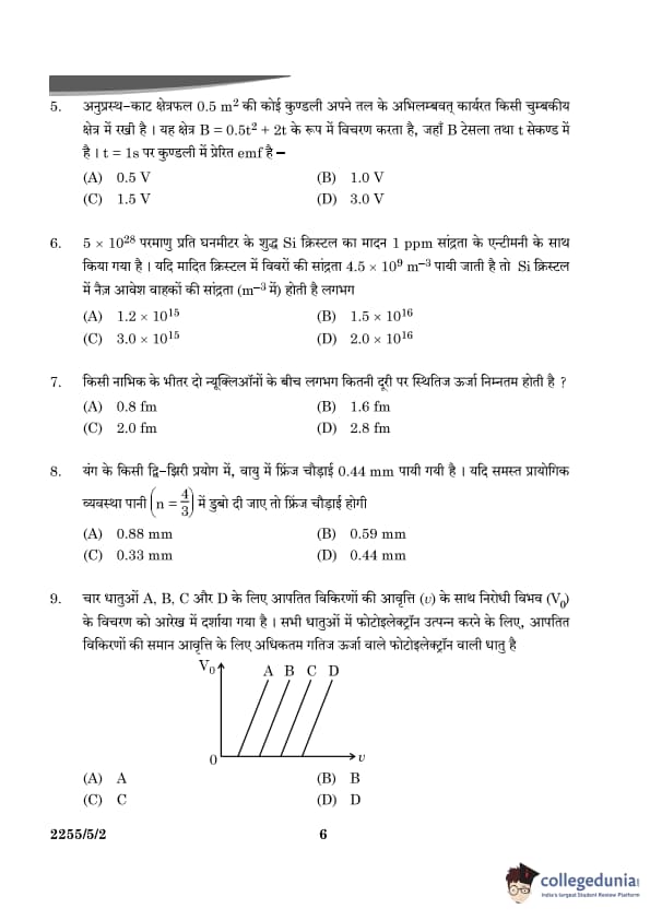
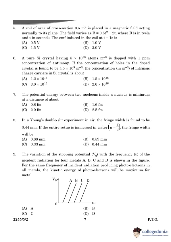
The variation of the stopping potential \( V_0 \) with the frequency \( \nu \) of the incident radiation for four metals A, B, C, and D is shown in the figure. For the same frequency of incident radiation producing photo-electrons in all metals, the kinetic energy of photo-electrons will be maximum for which metal?

View Solution
The stopping potential \( V_0 \) in the photoelectric effect is related to the kinetic energy of the photo-electrons by the equation:
\[ K.E. = eV_0 \]
where:
- \( e \) is the charge of the electron,
- \( V_0 \) is the stopping potential.
The kinetic energy of the photo-electrons depends on the stopping potential, which is in turn related to the frequency of the incident radiation by the photoelectric equation:
\[ eV_0 = h\nu - \phi \]
where:
- \( h \) is Planck's constant,
- \( \nu \) is the frequency of the incident radiation,
- \( \phi \) is the work function of the metal.
From the equation, we observe that for a given frequency, the kinetic energy of the photo-electrons will be maximum for the metal that has the largest stopping potential \( V_0 \), as it will correspond to the greatest kinetic energy.
Thus, from the given data, the metal that shows the highest value of stopping potential at the same frequency will have the maximum kinetic energy of the photo-electrons. Based on the graph, metal \( A \) shows the highest stopping potential.
Hence, the kinetic energy of photo-electrons will be maximum for metal A. Quick Tip: The stopping potential is directly related to the kinetic energy of the photo-electrons. A higher stopping potential corresponds to a higher kinetic energy.
The energy of an electron in the ground state of hydrogen atom is -13.6 eV. The kinetic and potential energy of the electron in the first excited state will be:
View Solution
For the hydrogen atom, the total energy of an electron in the \( n \)-th orbit is given by:
\[ E_n = - \frac{13.6 \, eV}{n^2} \]
where \( n \) is the principal quantum number.
- For the ground state (\( n = 1 \)), the energy is \( E_1 = -13.6 \, eV \).
- For the first excited state (\( n = 2 \)), the energy is:
\[ E_2 = - \frac{13.6 \, eV}{2^2} = - \frac{13.6 \, eV}{4} = -6.8 \, eV \]
The total energy \( E \) is the sum of kinetic energy (\( K \)) and potential energy (\( U \)):
\[ E = K + U \]
For a hydrogen atom:
- The kinetic energy (\( K \)) is equal to the negative of half the total energy:
\[ K = - \frac{E}{2} = - \frac{-6.8 \, eV}{2} = +3.4 \, eV \]
- The potential energy (\( U \)) is twice the total energy:
\[ U = 2 \cdot E = 2 \cdot (-6.8 \, eV) = -13.6 \, eV \]
Thus, the kinetic energy is \( +3.4 \, eV \), and the potential energy is \( -6.8 \, eV \). Quick Tip: In the hydrogen atom, the total energy is negative, and the kinetic energy is always positive and equal in magnitude to half the potential energy but with the opposite sign.
The electromagnetic waves used to purify water are:
View Solution
Ultraviolet (UV) rays are commonly used to purify water because they have germicidal properties. UV light damages the DNA or RNA of microorganisms, rendering them incapable of reproduction, effectively killing or inactivating harmful bacteria and viruses. This makes UV rays highly effective for water purification processes. Quick Tip: UV rays are used for disinfection as they can destroy microorganisms at the DNA level without the use of chemicals.
The focal lengths of the objective and the eyepiece of a compound microscope are 1 cm and 2 cm respectively. If the tube length of the microscope is 10 cm, the magnification obtained by the microscope for most suitable viewing by relaxed eye is:
View Solution
The magnification \( M \) of a compound microscope is given by the formula:
\[ M = \left( \frac{L}{f_0} \right) \cdot \left( 1 + \frac{D}{f_e} \right) \]
where:
- \( L \) is the tube length,
- \( f_0 \) is the focal length of the objective lens,
- \( f_e \) is the focal length of the eyepiece lens,
- \( D \) is the least distance of distinct vision (typically \( D = 25 \, cm \)).
Substituting the values:
- \( L = 10 \, cm \),
- \( f_0 = 1 \, cm \),
- \( f_e = 2 \, cm \),
- \( D = 25 \, cm \),
\[ M = \left( \frac{10}{1} \right) \cdot \left( 1 + \frac{25}{2} \right) \]
\[ M = 10 \cdot \left( 1 + 12.5 \right) = 10 \cdot 12.5 = 125 \]
Thus, the magnification is approximately \( \boxed{125} \), matching the correct option. Quick Tip: The total magnification of a compound microscope depends on the tube length and the focal lengths of the objective and eyepiece.
Assertion (A): An alpha particle is moving towards a gold nucleus. The impact parameter is maximum for the scattering angle of 180°.
Reason (R): The impact parameter in an alpha particle scattering experiment does not depend upon the atomic number of the target nucleus.
View Solution
Assertion (A):
In Rutherford scattering, the impact parameter corresponds to the perpendicular distance between the incoming particle's velocity vector and the center of the target nucleus. The impact parameter is maximum for the scattering angle of 90°, not 180°. When the scattering angle is 180°, the particle is scattered directly backward, but the maximum impact parameter occurs at a 90° deflection, not at 180°. Hence, Assertion (A) is false.
Reason (R):
The impact parameter in alpha particle scattering experiments is indeed influenced by the atomic number of the target nucleus, as the Coulomb force depends on the charge (atomic number) of the nucleus. Thus, Reason (R) is also false.
Since both Assertion (A) and Reason (R) are false, the correct answer is (D). Quick Tip: The maximum impact parameter corresponds to a scattering angle of 90°, not 180°. Also, the impact parameter is affected by the charge of the nucleus.
Assertion (A): In a Young's double-slit experiment, interference pattern is not observed when two coherent sources are infinitely close to each other.
Reason (R): The fringe width is proportional to the separation between the two sources.
View Solution
Assertion (A):
In a Young's double-slit experiment, interference is observed when the two sources are coherent and have a significant separation. If the two sources are infinitely close, the fringe width becomes so small that it becomes impossible to observe the interference pattern. Thus, Assertion (A) is true.
Reason (R):
The fringe width in Young's double-slit experiment is proportional to the wavelength of the light and the distance between the screen and the slits, but not the separation between the sources. The separation between the slits (not the sources) determines the fringe width. Therefore, Reason (R) is false.
Thus, the correct answer is (C): Assertion (A) is true, but Reason (R) is false. Quick Tip: In Young's double-slit experiment, the fringe width depends on the separation between the slits, not the sources.
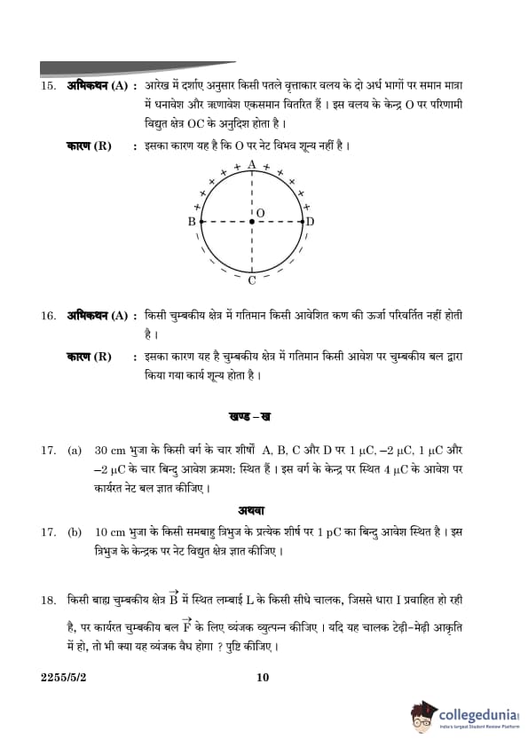
Assertion (A): Equal amount of positive and negative charges are distributed uniformly on two halves of a thin circular ring as shown in figure. The resultant electric field at the center O of the ring is along OC.
Reason (R): It is so because the net potential at O is not zero.

View Solution
Assertion (A):
When equal amounts of positive and negative charges are distributed uniformly on two halves of a thin circular ring, the net electric field at the center of the ring is along the axis, as the contributions from each half of the ring add up in that direction.
- The electric field contributions from both halves of the ring are directed along the line joining the center (O) to the axis (OC), and their magnitudes add up.
- This results in a net electric field along OC.
Thus, Assertion (A) is true.
Reason (R):
The net potential at the center of the ring is actually zero, as the positive and negative charge distributions cancel each other out in terms of potential (but not electric field).
- In electrostatics, the electric potential due to a charge distribution is a scalar quantity, and the potential from each half of the ring cancels out at the center due to symmetry.
- Therefore, the net potential at the center is zero, not non-zero.
Thus, Reason (R) is false.
Conclusion:
Since Assertion (A) is true and Reason (R) is false, the correct answer is (C). Quick Tip: In a symmetric charge distribution, the electric field at the center is non-zero along the axis, but the potential is zero because of the cancellation of contributions from each half of the ring.
Assertion (A): The energy of a charged particle moving in a magnetic field does not change.
Reason (R): It is because the work done by the magnetic force on the charge moving in a magnetic field is zero.
View Solution
Assertion (A):
The energy of a charged particle moving in a magnetic field remains constant. This is because the magnetic force acting on a charged particle is always perpendicular to the velocity of the particle. Since the force is perpendicular to the direction of motion, it does no work on the particle. Work is required to change the energy of a system, and since no work is done by the magnetic force, the energy of the particle does not change. Hence, Assertion (A) is true.
Reason (R):
The work done by a force is given by:
\[ W = \vec{F} \cdot \vec{d} \]
Since the magnetic force on a charged particle is always perpendicular to its velocity, the dot product \( \vec{F} \cdot \vec{d} = 0 \). This means that the magnetic force does no work on the particle, which is the reason why the energy of the particle remains unchanged. Hence, Reason (R) is true, and it correctly explains Assertion (A).
Thus, the correct answer is (A): Both Assertion (A) and Reason (R) are true, and Reason (R) is the correct explanation of Assertion (A). Quick Tip: The magnetic force on a charged particle is perpendicular to its velocity, so it does no work and does not change the particle's kinetic energy.
(a) Four point charges of 1 μC, -2 μC, 1 μC, and -2 μC are placed at the corners A, B, C, and D respectively, of a square of side 30 cm. Find the net force acting on a charge of 4 μC placed at the center of the square.
View Solution
The charges are arranged in a square, and the charge of 4 μC is placed at the center. We can calculate the net force on the charge by considering the forces due to each of the four point charges acting on it.

- The force on the charge at the center due to a point charge is given by Coulomb's law:
\[ F = k \frac{|q_1 q_2|}{r^2} \]
where:
- \( k \) is Coulomb's constant (\( k = 9 \times 10^9 \, Nm^2/C^2 \)),
- \( q_1 \) and \( q_2 \) are the magnitudes of the charges,
- \( r \) is the distance between the charges.
Each charge acts at a distance of \( r = \frac{side of square}{\sqrt{2}} = \frac{30 \, cm}{\sqrt{2}} = 21.21 \, cm = 0.2121 \, m \).
Now, calculate the individual forces for each pair of charges:
1. Force due to the charge of 1 μC at A: \[ F_1 = k \frac{|(4 \, \muC)(1 \, \muC)|}{(0.2121)^2} \]
2. Force due to the charge of -2 μC at B: \[ F_2 = k \frac{|(4 \, \muC)(-2 \, \muC)|}{(0.2121)^2} \]
And similarly for the charges at C and D.
After calculating the vector sum of all the forces, we obtain the net force on the charge at the center. Quick Tip: To calculate the net force, find the individual forces due to each charge and then add the vectors considering the direction of each force.
(b) Three point charges, 1 pC each, are kept at the vertices of an equilateral triangle of side 10 cm. Find the net electric field at the centroid of the triangle.
View Solution
The electric field due to a point charge at a distance \( r \) is given by:
\[ E = k \frac{|q|}{r^2} \]

Since all three charges are equal and placed at the vertices of an equilateral triangle, the symmetry of the problem simplifies the calculation. The electric fields due to each charge at the centroid of the triangle will have the same magnitude but different directions.
- The distance from the centroid of the equilateral triangle to each vertex is:
\[ r = \frac{10 \, cm}{\sqrt{3}} = 5.77 \, cm = 0.0577 \, m \]
- The magnitude of the electric field due to each charge is:
\[ E = k \frac{|q|}{r^2} \]
The net electric field is the vector sum of the electric fields due to each charge. Given the symmetry of the setup, the components of the electric fields in the directions perpendicular to the sides of the triangle will cancel out, and the resultant electric field will be along the line of symmetry.
After performing the vector addition, the net electric field at the centroid is:
\[ E_{net} = Total magnitude of electric field \] Quick Tip: In symmetric problems, like this one, use symmetry to simplify the calculation of the net electric field.
Derive an expression for magnetic force \( F \) acting on a straight conductor of length \( L \) carrying current \( I \) in an external magnetic field \( B \). Is it valid when the conductor is in zig-zag form? Justify.
View Solution
The magnetic force on a straight conductor of length \( L \) carrying a current \( I \) in an external magnetic field \( B \) is given by:
\[ F = BIL \sin \theta \]
where:
- \( B \) is the magnetic field strength,
- \( I \) is the current in the conductor,
- \( L \) is the length of the conductor in the magnetic field,
- \( \theta \) is the angle between the magnetic field and the direction of the current.
For a straight conductor, this equation gives the force in the direction perpendicular to both the current and the magnetic field.
When the conductor is in a zig-zag form, the effective length \( L \) in the magnetic field is still the total length of the conductor, but the direction of the magnetic force may vary at different points along the conductor. In this case, the total force can be calculated by summing the forces on each straight segment of the zig-zag conductor. The magnetic force formula remains valid, but the angle \( \theta \) and direction of the force will vary along the conductor. Quick Tip: The magnetic force on a conductor depends on the current, magnetic field, and the orientation of the conductor. For a zig-zag conductor, consider the total length and the changing direction of the magnetic force.
The radius of curvature of a convex mirror is 30 cm. It forms an image of an object which is half the size of the object. Find the separation between the object and the image.
View Solution
For a convex mirror, the mirror equation is:
\[ \frac{1}{f} = \frac{1}{u} + \frac{1}{v} \]
where:
\( f \) is the focal length of the mirror,
\( u \) is the object distance,
\( v \) is the image distance.
The focal length \( f \) is related to the radius of curvature \( R \) by:
\[ f = \frac{R}{2} \]
Given that the radius of curvature \( R = 30 \, cm \), the focal length is:
\[ f = \frac{30}{2} = 15 \, cm \]
The magnification \( m \) for the mirror is given by:
\[ m = \frac{Image Height}{Object Height} = \frac{v}{u} \]
Since the image is half the size of the object, the magnification is \( m = -\frac{1}{2} \) (negative for a virtual image in a convex mirror). Using the magnification equation:
\[ \frac{v}{u} = -\frac{1}{2} \]
Thus, \( v = -\frac{u}{2} \).
Substitute this into the mirror equation to find the separation between the object and the image. Quick Tip: For convex mirrors, the image formed is always virtual and smaller than the object, and the magnification is negative.
Calculate the energy released/absorbed (in MeV) in the nuclear reaction:
\[ ^1_1H + ^3_1H \rightarrow ^2_1H + ^2_1H \]
Given: \[ m(^1_1\text{H) = 1.007825 \, \mu, \, m(^2_1H) = 2.014102 \, \mu, \, m(^3_1H) = 3.016049 \, \mu \]
View Solution
To calculate the energy released or absorbed in the given nuclear reaction, we need to find the mass defect and then convert it to energy using Einstein's mass-energy equivalence equation:
\[ E = \Delta m \, c^2 \]
Where:
\( E \) is the energy released/absorbed,
\( \Delta m \) is the mass defect,
\( c \) is the speed of light.
First, calculate the mass defect for the reaction. The total mass before the reaction is the sum of the masses of \( ^1_1H \) and \( ^3_1H \), and the total mass after the reaction is the sum of the masses of the two \( ^2_1H \) nuclei.
\[ \Delta m = \left[ m(^1_1H) + m(^3_1H) \right] - 2 \cdot m(^2_1H) \]
Substituting the given values:
\[ \Delta m = \left[ 1.007825 + 3.016049 \right] - 2 \cdot 2.014102 \] \[ \Delta m = 4.023874 - 4.028204 \] \[ \Delta m = -0.00433 \, \mu \]
To convert this mass defect to energy, we use the conversion factor:
\[ 1 \, \mu = 931.5 \, MeV/c^2 \]
Thus, the energy released is:
\[ E = 0.00433 \, \mu \cdot 931.5 \, MeV/c^2 \] \[ E = 4.04 \, MeV \]
Therefore, the energy released in the nuclear reaction is 4.04 MeV. Quick Tip: The mass defect is the difference between the total mass of reactants and the total mass of products, which is converted into energy. The formula \( E = \Delta m \cdot c^2 \) links mass defect to energy.
A proton of energy 1.6 MeV approaches a gold nucleus (Z = 79). Find the distance of its closest approach.
View Solution
To calculate the distance of closest approach, we use the formula for the potential energy of a system where the proton is repelled by the nucleus:
\[ K.E. = \frac{1}{4 \pi \varepsilon_0} \cdot \frac{Z e^2}{r} \]
Where:
\( K.E. \) is the kinetic energy of the proton (1.6 MeV),
\( Z \) is the atomic number of gold (79),
\( e \) is the elementary charge,
\( \varepsilon_0 \) is the permittivity of free space (\(8.854 \times 10^{-12} \, C^2/N \cdot m^2\)),
\( r \) is the distance of closest approach.
Rearranging for \( r \):
\[ r = \frac{1}{4 \pi \varepsilon_0} \cdot \frac{Z e^2}{K.E.} \]
Substitute the known values:
\[ r = \frac{(8.854 \times 10^{-12}) \cdot (79 \cdot (1.6 \times 10^{-19})^2)}{(1.6 \times 10^6) \, eV} \cdot in SI units \]
\[ r \approx 4.6 \times 10^{-14} \, m \]
Therefore, the distance of closest approach is approximately 4.6 × 10⁻¹⁴ m. Quick Tip: The closest approach distance is derived using the conservation of energy principle, where the kinetic energy of the proton is converted into potential energy at the closest point of approach.
A photosensitive surface of work function 2.1 eV is irradiated by radiation of wavelength 150 nm. Calculate:
(i) the threshold wavelength,
(ii) energy (in eV) of an incident photon, and
(iii) maximum kinetic energy of emitted photoelectron.
View Solution
(i) Threshold Wavelength:
The threshold wavelength is the wavelength of light below which photoelectrons are emitted. It is given by:
\[ \lambda_{threshold} = \frac{hc}{\phi} \]
Where:
\( h \) is Planck's constant \( (6.626 \times 10^{-34} \, J·s) \),
\( c \) is the speed of light \( (3 \times 10^8 \, m/s) \),
\( \phi \) is the work function of the material \( (2.1 \, eV) \).
First, convert the work function to joules:
\[ \phi = 2.1 \, eV = 2.1 \times 1.602 \times 10^{-19} \, J \]
Now calculate the threshold wavelength:
\[ \lambda_{threshold} = \frac{6.626 \times 10^{-34} \cdot 3 \times 10^8}{2.1 \times 1.602 \times 10^{-19}} \]
\[ \lambda_{threshold} \approx 5.88 \times 10^{-7} \, m = 588 \, nm \]
(ii) Energy of the Incident Photon:
The energy of the incident photon can be calculated using the equation:
\[ E_{photon} = \frac{hc}{\lambda} \]
Substitute the given wavelength \( \lambda = 150 \, nm = 150 \times 10^{-9} \, m \):
\[ E_{photon} = \frac{6.626 \times 10^{-34} \cdot 3 \times 10^8}{150 \times 10^{-9}} \approx 1.33 \times 10^{-18} \, J \]
Now convert the energy from joules to eV:
\[ E_{photon} = \frac{1.33 \times 10^{-18}}{1.602 \times 10^{-19}} \approx 8.3 \, eV \]
(iii) Maximum Kinetic Energy of Emitted Photoelectron:
The maximum kinetic energy of the emitted photoelectron is given by:
\[ K.E. = E_{photon} - \phi \]
Substitute the values:
\[ K.E. = 8.3 \, eV - 2.1 \, eV = 6.2 \, eV \]
Thus, the maximum kinetic energy of the emitted photoelectron is 6.2 eV. Quick Tip: The energy of the incident photon must exceed the work function of the material for photoelectron emission to occur. The excess energy is converted into the kinetic energy of the emitted photoelectron.
State Lenz’s Law. In a closed circuit, the induced current opposes the change in magnetic flux that produced it as per the law of conservation of energy. Justify.
View Solution
Lenz's Law states that the direction of the induced current in a closed circuit is such that it opposes the change in magnetic flux that produces it. This is a consequence of the law of conservation of energy.
The justification comes from the principle that energy cannot be created or destroyed, only transformed. If the induced current were to flow in the same direction as the change in magnetic flux, it would lead to a gain in energy from nowhere, violating the conservation of energy. By opposing the change, the system ensures that the energy is conserved, preventing any spontaneous creation of energy. Quick Tip: Lenz’s law is essentially a consequence of conservation of energy, ensuring that the induced current does not violate energy principles.
A metal rod of length 2 m is rotated with a frequency of 60 rev/s about an axis passing through its centre and perpendicular to its length. A uniform magnetic field of 2T perpendicular to its plane of rotation is switched-on in the region. Calculate the e.m.f. induced between the centre and the end of the rod.
View Solution
The e.m.f. induced in the rod can be calculated using the formula for induced e.m.f. in a rotating rod in a magnetic field:
\[ \varepsilon = B \cdot \omega \cdot r^2 \]
Where:
\( B \) is the magnetic field strength (2 T),
\( \omega \) is the angular velocity of the rod,
\( r \) is the distance from the center of the rod to the point where the e.m.f. is measured.
First, calculate the angular velocity \( \omega \) using the given frequency:
\[ \omega = 2 \pi f = 2 \pi \times 60 = 120 \pi \, rad/s \]
Now, using the formula for e.m.f., where the distance \( r = 1 \, m \) (half of the rod length):
\[ \varepsilon = 2 \cdot 120 \pi \cdot 1^2 \]
\[ \varepsilon = 240 \pi \, V \]
So, the induced e.m.f. is approximately:
\[ \varepsilon \approx 754 \, V \] Quick Tip: When a conducting rod rotates in a magnetic field, the e.m.f. induced is directly proportional to the angular velocity and the square of the distance from the center.
State and explain Ampere’s circuital law.
View Solution
Ampere’s Circuital Law states that the line integral of the magnetic field \( \vec{B} \) around a closed loop is equal to the permeability of free space \( \mu_0 \) times the total current passing through the loop:
\[ \oint \vec{B} \cdot d\vec{l} = \mu_0 I \]
Where:
\( \oint \vec{B} \cdot d\vec{l} \) is the circulation of the magnetic field along a closed path,
\( I \) is the total current passing through the loop,
\( \mu_0 \) is the permeability of free space.
This law relates the magnetic field around a closed loop to the current passing through the loop, essentially showing that current creates a magnetic field. Quick Tip: Ampere’s circuital law helps calculate the magnetic field due to a current by considering the loop surrounding the current.
Two long straight parallel wires separated by 20 cm carry 5 A and 10 A current respectively, in the same direction. Find the magnitude and direction of the net magnetic field at a point midway between them.
View Solution
The magnetic field due to a current in a straight wire is given by:
\[ B = \frac{\mu_0 I}{2 \pi r} \]
Where:
\( I \) is the current in the wire,
\( r \) is the distance from the wire,
\( \mu_0 \) is the permeability of free space.
For two parallel wires with currents in the same direction, the magnetic fields at the midpoint add up. First, calculate the magnetic field at the midpoint due to each wire.
For wire 1 (carrying 5 A), the distance is \( r_1 = 10 \, cm = 0.1 \, m \):
\[ B_1 = \frac{\mu_0 \times 5}{2 \pi \times 0.1} = \frac{4 \pi \times 10^{-7} \times 5}{2 \pi \times 0.1} = 1 \times 10^{-5} \, T \]
For wire 2 (carrying 10 A), the distance is also \( r_2 = 0.1 \, m \):
\[ B_2 = \frac{\mu_0 \times 10}{2 \pi \times 0.1} = \frac{4 \pi \times 10^{-7} \times 10}{2 \pi \times 0.1} = 2 \times 10^{-5} \, T \]
Since the currents are in the same direction, the magnetic fields will add up:
\[ B_{net} = B_1 + B_2 = 1 \times 10^{-5} + 2 \times 10^{-5} = 3 \times 10^{-5} \, T \]
The direction of the magnetic field is determined by the right-hand rule. For currents in the same direction, the magnetic fields at the midpoint will point in the direction of the right hand curl. The field will be directed upwards at the midpoint. Quick Tip: For two parallel wires with currents in the same direction, the magnetic fields at the midpoint add up and point in the direction of the right-hand rule.
Define 'temperature coefficient of resistance' of a metal.
View Solution
The temperature coefficient of resistance (denoted by \( \alpha \)) of a metal is defined as the fractional change in resistance per unit change in temperature. It is given by the equation:
\[ \alpha = \frac{1}{R_0} \frac{dR}{dT} \]
Where:
\( R_0 \) is the resistance at some reference temperature,
\( \frac{dR}{dT} \) is the rate of change of resistance with respect to temperature.
In other words, it measures how much the resistance of the material changes with a unit change in temperature. Quick Tip: The temperature coefficient of resistance is typically positive for metals, indicating that resistance increases with temperature.
Show the variation of resistivity of copper with rise in temperature.
View Solution
The resistivity of copper increases with temperature. This relationship is approximately linear for a small temperature range. The resistivity \( \rho \) at temperature \( T \) is given by:

\[ \rho_T = \rho_0 \left( 1 + \alpha (T - T_0) \right) \]
Where:
\( \rho_T \) is the resistivity at temperature \( T \),
\( \rho_0 \) is the resistivity at a reference temperature \( T_0 \),
\( \alpha \) is the temperature coefficient of resistivity for copper,
\( (T - T_0) \) is the change in temperature.
For copper, \( \alpha \) is approximately \( 0.00393 \, °C^{-1} \). As temperature increases, the resistivity increases almost linearly. Quick Tip: Copper is a good conductor, but its resistivity still increases with temperature, which is a typical property of metals.
The resistance of a wire is 10 \(\Omega\) at 27°C. Find its resistance at -73°C. The temperature coefficient of resistance of the material of the wire is \( 1.70 \times 10^{-4} \, °C^{-1} \).
View Solution
We can calculate the resistance at a new temperature using the formula:
\[ R_T = R_0 \left( 1 + \alpha (T - T_0) \right) \]
Where:
\( R_T \) is the resistance at the new temperature \( T \),
\( R_0 \) is the resistance at the reference temperature \( T_0 \),
\( \alpha \) is the temperature coefficient of resistance,
\( T - T_0 \) is the change in temperature.
Given:
\( R_0 = 10 \, \Omega \),
\( T_0 = 27^\circ C \),
\( T = -73^\circ C \),
\( \alpha = 1.70 \times 10^{-4} \, °C^{-1} \).
Substitute into the equation:
\[ R_T = 10 \left( 1 + 1.70 \times 10^{-4} \times (-73 - 27) \right) \]
\[ R_T = 10 \left( 1 + 1.70 \times 10^{-4} \times (-100) \right) \]
\[ R_T = 10 \left( 1 - 0.017 \right) \]
\[ R_T = 10 \times 0.983 = 9.83 \, \Omega \]
So, the resistance at -73°C is approximately \( 9.83 \, \Omega \). Quick Tip: The resistance decreases with a decrease in temperature for materials with a positive temperature coefficient of resistance.
Name the part of the electromagnetic spectrum which are stopped by face mask worn by welders.
View Solution
The part of the electromagnetic spectrum that is stopped by the face mask worn by welders is Ultraviolet (UV) radiation. Welders wear face masks with special glasses that block UV rays, which are harmful to the eyes and skin. Quick Tip: Face masks worn by welders block UV radiation, which can cause serious eye damage and skin burns.
Name the part of the electromagnetic spectrum which is used in detectors in Earth satellites.
View Solution
The part of the electromagnetic spectrum used in detectors on Earth satellites is Microwaves. These are used in satellite communication, weather forecasting, and remote sensing. Quick Tip: Microwaves are widely used in communication systems and satellite detectors due to their ability to penetrate the Earth's atmosphere.
Name the part of the electromagnetic spectrum which is used in the 'short-wave band' in communication.
View Solution
The part of the electromagnetic spectrum used in the 'short-wave band' in communication is Short-Wave Radio Waves (SW). These are used for long-range communication as they can reflect off the ionosphere. Quick Tip: Short-wave radio waves are important for long-range communication due to their ability to bounce off the ionosphere.
Explain the characteristics of a p-n junction diode that makes it suitable for its use as a rectifier.
View Solution
A p-n junction diode is ideal for use as a rectifier because of the following characteristics:
1. Uni-directional Conduction: In a p-n junction diode, the current can flow in only one direction when the diode is forward-biased (p-type connected to positive, n-type connected to negative). In reverse bias, the current does not flow, which is essential for rectification.
2. Forward Bias and Reverse Bias: When forward biased, the p-n junction reduces the potential barrier, allowing current to flow. In reverse bias, the potential barrier increases, preventing current from flowing, except for a very small leakage current.
3. Rectification: This characteristic of allowing current to flow only in one direction makes the p-n junction diode suitable for rectification purposes, where alternating current (AC) is converted into direct current (DC). Quick Tip: The ability of the p-n junction diode to allow current to flow only in the forward direction makes it an effective rectifier.
With the help of a circuit diagram, explain the working of a full-wave rectifier.
View Solution
A full-wave rectifier converts both halves of the AC input into pulsating DC. It uses two diodes in a bridge configuration.

Working of Full-Wave Rectifier:
1. Positive Half-Cycle of AC Input: During the positive half cycle of AC, diode D1 conducts, allowing current to pass through the load resistor \( R \). At the same time, diode D2 is reverse biased and does not conduct.
2. Negative Half-Cycle of AC Input: During the negative half cycle, diode D2 conducts, allowing current to pass through the load resistor in the same direction as during the positive half cycle. Diode D1 is reverse biased and does not conduct.
Thus, the output across the load resistor is always in one direction, producing a full-wave rectified output. Quick Tip: A full-wave rectifier ensures that current flows in the same direction during both half cycles, making the output smoother.
Explain the following, giving reasons: (a) A doped semiconductor is electrically neutral.
View Solution
In a doped semiconductor, the number of electrons and holes is balanced. The doping process adds extra electrons (for n-type) or creates holes (for p-type), but these do not affect the overall neutrality of the semiconductor. The added charge carriers are balanced by the opposite charge in the crystal structure, ensuring that the semiconductor remains electrically neutral overall. Quick Tip: Doping creates charge carriers but does not change the overall neutrality of the semiconductor because the added carriers are balanced.
(b) In a p-n junction under equilibrium, there is no net current.
View Solution
At equilibrium, the diffusion current (due to the movement of charge carriers from high concentration to low concentration) is balanced by the drift current (due to the electric field inside the junction). This results in no net current flow. The depletion region acts as an insulator, preventing the movement of charge carriers, and hence no current flows in the equilibrium state. Quick Tip: In equilibrium, the diffusion and drift currents cancel each other out, resulting in no net current flow.
Reverse current is limited due to concentration of minority charge carriers on either side of the junction.
View Solution
In a p-n junction, under normal conditions, when the junction is reverse biased, the majority charge carriers (electrons in the n-region and holes in the p-region) are not able to move across the junction. However, the minority charge carriers (holes in the n-region and electrons in the p-region) are still able to move, but in very small quantities.
This movement of minority carriers in the reverse direction causes a small reverse current, known as the **reverse saturation current**. The concentration of minority charge carriers on either side of the junction is limited, and thus the reverse current remains very small.
As the reverse voltage increases, more minority carriers are pulled across the junction, but the reverse current cannot increase significantly beyond a certain point due to the limited concentration of these carriers. Once the reverse bias reaches a critical value (known as the breakdown voltage), the reverse current can increase dramatically, but normally, the reverse current is limited by the concentration of minority carriers.
Thus, the reverse current is limited due to the finite number of minority charge carriers in the p and n regions. Quick Tip: Reverse current is limited : the finite number of minority charge carriers in the p and n regions.
An electron moving with a velocity \( v = (1.0 \times 10^7 \, m/s)i + (0.5 \times 10^7 \, m/s)j \) enters a region of uniform magnetic field \( B = (0.5 \, mT)j \). Find the radius of the circular path described by it. While rotating, does the electron trace a linear path too? If so, calculate the linear distance covered by it during the period of one revolution.
View Solution
The magnetic force on the electron is given by:
\[ F = qvB \]
For circular motion, this force provides the centripetal force:
\[ \frac{mv^2}{r} = qvB \]
Thus, the radius of the path is:
\[ r = \frac{mv}{qB} \]
Given:
\( m = 9.11 \times 10^{-31} \, kg \) (mass of electron),
\( v = 1.0 \times 10^7 \, m/s \),
\( q = 1.6 \times 10^{-19} \, C \) (charge of electron),
\( B = 0.5 \times 10^{-3} \, T \).
Substituting these values:
\[ r = \frac{(9.11 \times 10^{-31} \, kg)(1.0 \times 10^7 \, m/s)}{(1.6 \times 10^{-19} \, C)(0.5 \times 10^{-3} \, T)} \]
\[ r = 0.1139 \, m \]
Thus, the radius of the circular path is \( r = 0.1139 \, m \).
Linear distance: The electron moves in a circular path, and the linear distance covered in one revolution is the circumference of the circle:
\[ Linear distance = 2\pi r = 2\pi \times 0.1139 \, m = 0.715 \, m \]
So, the electron traces a circular path and covers a linear distance of \( 0.715 \, m \) in one revolution. Quick Tip: The radius of the circular path of a charged particle in a magnetic field depends on its velocity, charge, and the strength of the magnetic field.
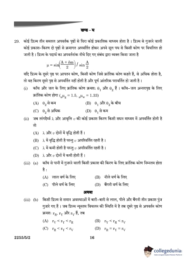
Question 29:
A prism is an optical medium bounded by three refracting plane surfaces. A ray of
light suffers successive refractions on passing through its two surfaces and deviates by a
certain angle from its original path. The refractive index of the material of the prism is
given by:
If the angle of incidence on the second surface is greater than an angle called the
critical angle, the ray will not be refracted from the second surface and is totally
internally reflected.
29(i). The critical angle for glass is \( \theta_1 \) and that for water is \( \theta_2 \). The critical angle for the glass-water surface would be (given \( \mu_g = 1.5, \mu_w = 1.33 \)):
View Solution
The critical angle \( \theta_c \) for total internal reflection at the interface between two media is given by the formula:
\[ \sin \theta_c = \frac{n_2}{n_1} \]
where \( n_1 \) is the refractive index of the denser medium and \( n_2 \) is the refractive index of the rarer medium. The critical angle for the glass-water surface can be determined by using the refractive indices of glass and water.
Given:
- Refractive index of glass \( \mu_g = 1.5 \),
- Refractive index of water \( \mu_w = 1.33 \).
The critical angle for the glass-water surface is:
\[ \sin \theta_c = \frac{\mu_w}{\mu_g} = \frac{1.33}{1.5} = 0.8867 \]
Thus, \( \theta_c = \sin^{-1}(0.8867) \approx 62^\circ \).
We also know that:
- \( \theta_1 \), the critical angle for glass, corresponds to the interface between glass and air (where \( n_2 = 1 \) for air).
- \( \theta_2 \), the critical angle for water, corresponds to the interface between water and air.
Since \( \mu_g > \mu_w \), we find that the critical angle for the glass-water interface lies between the critical angles for glass and water, i.e., between \( \theta_1 \) and \( \theta_2 \).
Thus, the critical angle for the glass-water surface is between \( \theta_1 \) and \( \theta_2 \). Quick Tip: The critical angle depends on the refractive indices of the two media involved. Since glass has a higher refractive index than water, the critical angle for the glass-water surface will be between the critical angles of glass and water.
When a ray of light of wavelength \( \lambda \) and frequency \( \nu \) is refracted into a denser medium,
View Solution
When light enters a denser medium, its wavelength decreases due to the slower speed of light in the denser medium, while the frequency remains constant. The frequency of light is determined by the source and does not change upon refraction. Therefore, the wavelength decreases but the frequency remains unchanged.
Thus, the correct answer is that \( \lambda \) decreases but \( \nu \) is unchanged. Quick Tip: In a denser medium, light slows down, causing its wavelength to decrease, but the frequency remains constant because it depends on the source.
The critical angle for a ray of light passing from glass to water is minimum for
View Solution
The critical angle for a ray of light depends on the refractive indices of the two media. For shorter wavelengths, the refractive index is higher, which results in a smaller critical angle. Since violet light has the shortest wavelength in the visible spectrum, the refractive index for violet light is the highest, leading to the minimum critical angle for violet light.
Thus, the correct answer is violet colour. Quick Tip: Shorter wavelengths, like violet light, have higher refractive indices, leading to a smaller critical angle compared to longer wavelengths like red.
Three beams of red, yellow, and violet colours are passed through a prism, one by one under the same condition. When the prism is in the position of minimum deviation, the angles of refraction from the second surface are \( r_R, r_Y, \) and \( r_V \) respectively. Then,
View Solution
In a prism, the angle of deviation is dependent on the refractive index of the material for each wavelength of light. Since the refractive index increases with decreasing wavelength, the violet light (with the shortest wavelength) will refract the most, followed by the yellow and red light, which refracts the least. Therefore, the angles of refraction will be in the order:
\[ r_R < r_Y < r_V \]
Thus, the correct answer is \( r_R < r_Y < r_V \). Quick Tip: Shorter wavelengths of light, like violet, bend more in a prism due to higher refractive indices, while longer wavelengths like red bend less.
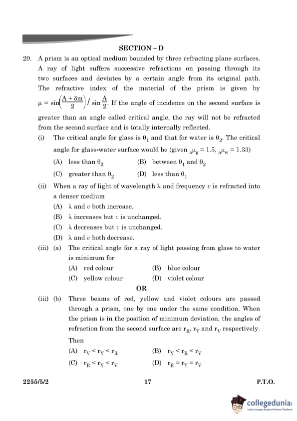
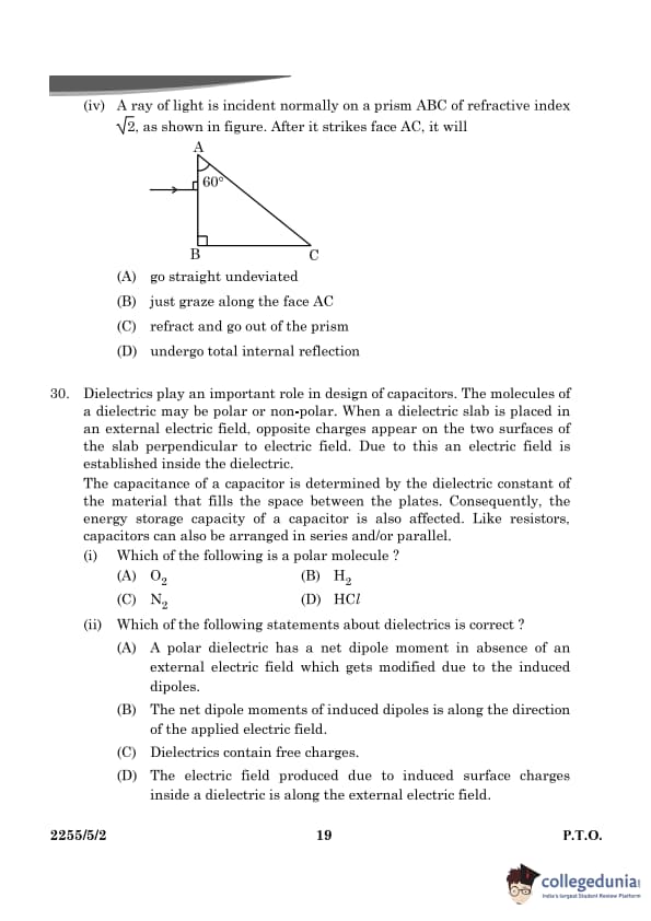
A ray of light is incident normally on a prism ABC of refractive index \( \sqrt{2} \), as shown in the figure. After it strikes face AC, it will

View Solution
For the ray to undergo total internal reflection at face AC, the angle of incidence at that face must exceed the critical angle. The critical angle \( \theta_c \) for total internal reflection is given by:
\[ \sin \theta_c = \frac{1}{\mu} \]
For a refractive index \( \mu = \sqrt{2} \), we find:
\[ \sin \theta_c = \frac{1}{\sqrt{2}} \implies \theta_c = 45^\circ \]
Since the ray strikes face AC normally, it will undergo total internal reflection if the angle of incidence at AC is greater than the critical angle. This leads to total internal reflection.
Thus, the correct answer is that the ray will undergo total internal reflection. Quick Tip: Total internal reflection occurs when the angle of incidence exceeds the critical angle, causing the light to reflect within the prism.
Question 30:
Dielectrics play an important role in the design of capacitors. The molecules of a
dielectric may be polar or non-polar. When a dielectric slab is placed in an external
electric field, opposite charges appear on the two surfaces of the slab perpendicular to
the electric field. Due to this, an electric field is established inside the dielectric. The
capacitance of a capacitor is determined by the dielectric constant of the material that
fills the space between the plates. Consequently, the energy storage capacity of a
capacitor is also affected. Like resistors, capacitors can also be arranged in series
and/or parallel.
30(i). Which of the following is a polar molecule?
View Solution
A polar molecule has a net dipole moment due to the difference in electronegativity between the atoms in the molecule. In the case of HCl, chlorine is more electronegative than hydrogen, resulting in a partial negative charge on chlorine and a partial positive charge on hydrogen. This creates a dipole moment, making HCl a polar molecule.
The other molecules, O\(_2\), H\(_2\), and N\(_2\), are non-polar because they consist of identical atoms with the same electronegativity, leading to no dipole moment. Quick Tip: A polar molecule has a dipole moment due to an unequal distribution of charge caused by differences in electronegativity.
Which of the following statements about dielectrics is correct?
View Solution
In the presence of an applied electric field, the dipoles in a dielectric material align with the field. The induced dipole moments are aligned along the direction of the applied electric field. This increases the overall dipole moment of the dielectric.
Statement (A) is incorrect because the net dipole moment in a polar dielectric is zero in the absence of an external electric field. Statement (C) is incorrect because dielectrics do not contain free charges, as they are insulating materials. Statement (D) is incorrect because the electric field inside a dielectric material due to induced charges is opposite to the external field. Quick Tip: In a dielectric material, the dipoles align with the external electric field, creating an induced dipole moment in the same direction.
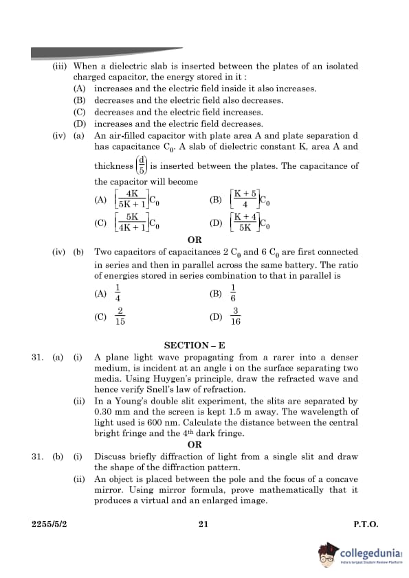
When a dielectric slab is inserted between the plates of an isolated charged capacitor, the energy stored in it:
View Solution
When a dielectric slab is inserted between the plates of an isolated charged capacitor, the capacitance increases. This is because the dielectric material reduces the effective electric field between the plates, resulting in a decrease in the energy stored in the capacitor. The energy stored in a capacitor is given by:
\[ U = \frac{Q^2}{2C} \]
where \( C \) is the capacitance. Since the dielectric increases the capacitance, the energy stored decreases. The electric field also decreases because the dielectric material polarizes and opposes the applied electric field. Quick Tip: Inserting a dielectric material between the plates of a capacitor increases its capacitance, which leads to a decrease in the stored energy and the electric field.
An air-filled capacitor with plate area A and plate separation d has capacitance \( C_0 \). A slab of dielectric constant \( K \), area A and thickness \( \frac{d}{2} \) is inserted between the plates. The capacitance of the capacitor will become:
(A) \( \frac{[4K]}{[4K+1]} C_0 \)
View Solution
The capacitance of a parallel plate capacitor without a dielectric is given by:
\[ C_0 = \frac{\varepsilon_0 A}{d} \]
When a dielectric is inserted, the capacitance changes depending on how the dielectric is distributed between the plates. Here, the dielectric has a thickness of \( \frac{d}{2} \) and covers the entire area of the plates.
The capacitance of the two regions formed by inserting the dielectric is:
1. The capacitance of the region with dielectric:
\[ C_1 = \frac{K \varepsilon_0 A}{\frac{d}{2}} = \frac{2K \varepsilon_0 A}{d} \]
2. The capacitance of the remaining region (without dielectric):
\[ C_2 = \frac{\varepsilon_0 A}{\frac{d}{2}} = \frac{2 \varepsilon_0 A}{d} \]
Now, these two capacitances \( C_1 \) and \( C_2 \) are in series, so the total capacitance is given by:
\[ \frac{1}{C} = \frac{1}{C_1} + \frac{1}{C_2} \]
Substituting the values of \( C_1 \) and \( C_2 \):
\[ \frac{1}{C} = \frac{1}{\frac{2K \varepsilon_0 A}{d}} + \frac{1}{\frac{2 \varepsilon_0 A}{d}} \]
Simplifying:
\[ \frac{1}{C} = \frac{d}{2K \varepsilon_0 A} + \frac{d}{2 \varepsilon_0 A} \]
\[ \frac{1}{C} = \frac{d}{2 \varepsilon_0 A} \left( \frac{4}{K} + 1 \right) \]
\[ C = \frac{2 \varepsilon_0 A}{d} \left( \frac{4K}{K+1} \right) \]
Thus, the capacitance with the dielectric is:
\[ C = \frac{4K}{4K+1} C_0 \]
Hence, the capacitance becomes \( \frac{[4K]}{[4K+1]} C_0 \) Quick Tip: The presence of a dielectric increases the capacitance by a factor of \( K \), depending on the thickness and area of the dielectric inserted.
Two capacitors of capacitances \( 2C_0 \) and \( 6C_0 \) are first connected in series and then in parallel across the same battery. The ratio of energies stored in series combination to that in parallel is:
View Solution
When capacitors are connected in series or parallel, the energy stored in them is different.
Energy Stored in Capacitors
The energy stored in a capacitor is given by:
\[ E = \frac{1}{6} C V^2 \]
where \( C \) is the capacitance and \( V \) is the potential across the capacitor.
Series Combination
For two capacitors \( C_1 = 2C_0 \) and \( C_2 = 6C_0 \), connected in series, the total capacitance \( C_{series} \) is given by:
\[ \frac{1}{C_{series}} = \frac{1}{C_1} + \frac{1}{C_2} \]
Substituting the values:
\[ \frac{1}{C_{series}} = \frac{1}{2C_0} + \frac{1}{6C_0} \]
\[ \frac{1}{C_{series}} = \frac{3}{6C_0} + \frac{1}{6C_0} = \frac{4}{6C_0} \]
\[ C_{series} = \frac{6C_0}{4} = 1.5 C_0 \]
Thus, the energy stored in the series combination is:
\[ E_{series} = \frac{1}{2} C_{series} V^2 = \frac{1}{2} \times 1.5 C_0 \times V^2 = 0.75 C_0 V^2 \]
Parallel Combination
For two capacitors connected in parallel, the total capacitance \( C_{parallel} \) is:
\[ C_{parallel} = C_1 + C_2 = 2C_0 + 6C_0 = 8C_0 \]
Thus, the energy stored in the parallel combination is:
\[ E_{parallel} = \frac{1}{2} C_{parallel} V^2 = \frac{1}{2} \times 8C_0 \times V^2 = 4 C_0 V^2 \]
Ratio of Energies
The ratio of energies stored in the series combination to that in the parallel combination is:
\[ \frac{E_{series}}{E_{parallel}} = \frac{0.75 C_0 V^2}{4 C_0 V^2} = \frac{0.75}{4} = \frac{1}{6} \]
Thus, the correct answer is \( \frac{1}{6} \). Quick Tip: The energy stored in capacitors connected in series is always less than when connected in parallel, due to the total capacitance being smaller in series.
A plane light wave propagating from a rarer into a denser medium, is incident at an angle \( i \) on the surface separating two media. Using Huygen's principle, draw the refracted wave and hence verify Snell's law of refraction.
View Solution
When a plane light wave passes from a rarer medium (such as air) to a denser medium (such as glass or water), refraction occurs. According to Huygen's principle, every point on the wavefront acts as a source of secondary wavelets that spread out in all directions. When the wavefront reaches the interface between the two media, the wavelets travel at different speeds in the two media due to their different refractive indices. This change in speed causes the wave to bend, which is observed as refraction.

Let \( n_1 \) be the refractive index of the rarer medium, and \( n_2 \) be the refractive index of the denser medium. The angle of incidence \( i \) and the angle of refraction \( r \) are related by Snell's law, which can be derived using Huygen's principle.
\[ \frac{\sin i}{\sin r} = \frac{n_2}{n_1} \]
This equation expresses the relationship between the angles of incidence and refraction and the refractive indices of the two media. Quick Tip: Huygen’s principle is a useful tool to explain refraction by considering each point on a wavefront as a source of secondary wavelets. Snell’s law can be derived from this principle by considering the change in the speed of light when moving between media of different refractive indices.
In a Young's double slit experiment, the slits are separated by 0.30 mm and the screen is kept 1.5 m away. The wavelength of light used is 600 nm. Calculate the distance between the central bright fringe and the 4th dark fringe.
View Solution
The fringe width \( \beta \) in a Young's double slit experiment is given by the formula:
\[ \beta = \frac{\lambda D}{d} \]
Where:
\(\lambda\) = wavelength of light = \( 600 \, nm = 600 \times 10^{-9} \, m \) \( D \) = distance between the slits and the screen = \( 1.5 \, m \) \( d \) = separation between the slits = \( 0.30 \, mm = 0.30 \times 10^{-3} \, m \)
Substitute the values into the formula to find the fringe width:
\[ \beta = \frac{600 \times 10^{-9} \times 1.5}{0.30 \times 10^{-3}} = \frac{900 \times 10^{-9}}{0.30 \times 10^{-3}} = 3 \times 10^{-3} \, m = 3 \, mm \]
The distance between the central bright fringe and the 4th dark fringe is \( 4 \) times the fringe width:
\[ Distance = 4 \times \beta = 4 \times 3 \, mm = 12 \, mm \]
Thus, the distance between the central bright fringe and the 4th dark fringe is \( 12 \, mm \). Quick Tip: In a Young’s double slit experiment, the distance between dark fringes is determined by the wavelength, the distance between the slits, and the screen distance. Use the formula to calculate the fringe positions.
Discuss briefly diffraction of light from a single slit and draw the shape of the diffraction pattern.
View Solution
Diffraction is the bending of light around obstacles or the spreading of light when it passes through small apertures. In the case of a single slit, when monochromatic light passes through the slit, it bends and spreads out. The diffraction pattern observed on a screen placed behind the slit consists of a central maximum and a series of secondary maxima and minima.
The condition for the minima in the diffraction pattern is given by:
\[ a \sin \theta = m \lambda \quad for \quad m = \pm 1, \pm 2, \pm 3, \dots \]
Where:
\( a \) = width of the slit
\( \theta \) = angle of diffraction
\( \lambda \) = wavelength of light
\( m \) = order of the minima
The central maximum is the brightest and widest, and the intensity decreases as we move away from the center. Quick Tip: In a single-slit diffraction pattern, the central maximum is the brightest, and the intensity decreases as we move to higher-order maxima.
An object is placed between the pole and the focus of a concave mirror. Using mirror formula, prove mathematically that it produces a virtual and an enlarged image.
View Solution
For a concave mirror, the mirror formula is:
\[ \frac{1}{f} = \frac{1}{v} + \frac{1}{u} \]
Where:
\( f \) = focal length of the mirror
\( v \) = image distance
\( u \) = object distance
When the object is placed between the pole (P) and the focus (F) of the concave mirror, the image formed is virtual, upright, and magnified. To prove this, consider the following:
1. The object is placed at a point where \( u < f \).
2. From the mirror formula, since \( \frac{1}{v} = \frac{1}{f} - \frac{1}{u} \), the value of \( v \) will be negative, indicating a virtual image.
3. The magnification \( m \) is given by:
\[ m = \frac{v}{u} \]
Since \( v \) is negative and \( |v| > |u| \), the magnification is greater than 1, indicating an enlarged image.
Thus, the image is virtual and magnified. Quick Tip: For a concave mirror, if the object is placed between the pole and the focus, the image formed is virtual, upright, and enlarged. The magnification is greater than 1.
Draw equipotential surfaces for an electric dipole.
View Solution

The equipotential surfaces of an electric dipole are the surfaces on which the electric potential is constant. For a dipole, the electric potential at any point due to the dipole is given by:
\[ V = \frac{1}{4\pi \epsilon_0} \left( \frac{p \cos \theta}{r^2} \right) \]
Where:
\( V \) = electric potential
\( p \) = dipole moment
\( \theta \) = angle between the position vector and the dipole axis
\( r \) = distance from the dipole
The equipotential surfaces for an electric dipole are a family of concentric spheres that become distorted near the dipole, with the dipole axis being the axis of symmetry. The surfaces near the dipole are more closely spaced, and they become farther apart as we move away from the dipole. Quick Tip: Equipotential surfaces are always perpendicular to the electric field lines and are con- centric spheres for a point charge. For a dipole, they form a more complex pattern.
Two point charges \( q_1 \) and \( q_2 \) are located at \( r_1 \) and \( r_2 \) respectively in an external electric field \( E \). Obtain an expression for the potential energy of the system.
View Solution
The potential energy \( U \) of a system of two point charges \( q_1 \) and \( q_2 \) in the presence of an external electric field \( E \) is the sum of the potential energies due to the interaction of the charges and the potential energy due to the external field.
The potential energy of the two charges due to their interaction is given by Coulomb's law:
\[ U_{interaction} = \frac{1}{4\pi \epsilon_0} \frac{q_1 q_2}{r_{12}} \]
Where: \( r_{12} \) = distance between the charges.
The potential energy due to the external electric field \( E \) acting on the charges is given by:
\[ U_{field} = - (q_1 \vec{r_1} + q_2 \vec{r_2}) \cdot \vec{E} \]
Thus, the total potential energy \( U_{total} \) of the system is:
\[ U_{total} = U_{interaction} + U_{field} = \frac{1}{4\pi \epsilon_0} \frac{q_1 q_2}{r_{12}} - (q_1 \vec{r_1} + q_2 \vec{r_2}) \cdot \vec{E} \] Quick Tip: When charges are placed in an external electric field, the total potential energy of the system includes both the energy due to the electric field and the interaction energy between the charges.
The dipole moment of a molecule is \( 10^{-30} \, Cm \). It is placed in an electric field \( E \) of \( 10^5 \, V/m \) such that its axis is along the electric field. The direction of \( E \) is suddenly changed by \( 60^\circ \) at an instant. Find the change in the potential energy of the dipole, at that instant.
View Solution
The potential energy of an electric dipole in a uniform electric field \( E \) is given by:
\[ U = - pE \cos \theta \]
Where:
\( p \) = dipole moment of the molecule
\( E \) = magnitude of the electric field
\( \theta \) = angle between the dipole moment and the electric field.
Initially, the dipole is aligned with the electric field, so \( \theta = 0^\circ \). The potential energy at this position is:
\[ U_{initial} = - pE \cos 0^\circ = - pE \]
When the direction of \( E \) is changed by \( 60^\circ \), the new angle becomes \( \theta = 60^\circ \). The potential energy at this position is:
\[ U_{final} = - pE \cos 60^\circ = - \frac{pE}{2} \]
Thus, the change in potential energy \( \Delta U \) is:
\[ \Delta U = U_{final} - U_{initial} = - \frac{pE}{2} - (- pE) = \frac{pE}{2} \]
Substitute \( p = 10^{-30} \, Cm \) and \( E = 10^5 \, V/m \):
\[ \Delta U = \frac{10^{-30} \times 10^5}{2} = 5 \times 10^{-26} \, J \]
Thus, the change in the potential energy is \( 5 \times 10^{-26} \, J \). Quick Tip: The potential energy of a dipole in an electric field depends on the angle between the dipole moment and the electric field. The energy change is proportional to the cosine of the angle between them.
A thin spherical shell of radius \( R \) has a uniform surface charge density \( \sigma \). Using Gauss' law, deduce an expression for the electric field:
(i) Outside the shell
View Solution
To find the electric field outside a uniformly charged spherical shell, we use Gauss' law. Consider a spherical Gaussian surface with radius \( r \) such that \( r > R \), where \( R \) is the radius of the spherical shell.

By symmetry, the electric field at any point outside the shell must be radially symmetric and have the same magnitude at all points on the Gaussian surface. The total charge enclosed by the Gaussian surface is:
\[ Q_{enc} = \sigma \cdot 4\pi R^2 \]
Applying Gauss' law:
\[ \oint \vec{E} \cdot d\vec{A} = \frac{Q_{enc}}{\epsilon_0} \]
Since the electric field is radial, the left-hand side simplifies to:
\[ E \cdot 4\pi r^2 = \frac{\sigma \cdot 4\pi R^2}{\epsilon_0} \]
Solving for \( E \):
\[ E = \frac{\sigma R^2}{\epsilon_0 r^2} \]
Thus, the electric field outside the spherical shell is:
\[ E_{outside} = \frac{\sigma R^2}{\epsilon_0 r^2} \] Quick Tip: Using Gauss’ law, the electric field inside a spherical shell is zero, while outside it behaves as if the entire charge were concentrated at the center.
Two long straight thin wires AB and CD have linear charge densities \( \lambda_1 = 10 \, \mu C/m \) and \( \lambda_2 = -20 \, \mu C/m \), respectively. They are kept parallel to each other at a distance of 1 m. Find the magnitude and direction of the net electric field at a point midway between them.
View Solution
The electric field due to a uniformly charged infinite wire is given by:
\[ E = \frac{2k \lambda}{r} \]
Where:
\( k = \frac{1}{4\pi \epsilon_0} \)
\( \lambda \) = linear charge density
\( r \) = distance from the wire
At the point midway between the two wires, the distance from each wire is \( r = \frac{1}{2} \, m \).
The electric field due to wire AB at this point is:
\[ E_1 = \frac{2k \lambda_1}{\frac{1}{2}} = 4k \lambda_1 \]
The electric field due to wire CD at this point is:
\[ E_2 = \frac{2k \lambda_2}{\frac{1}{2}} = 4k \lambda_2 \]
The direction of the electric fields will depend on the sign of the charge. Since \( \lambda_1 = 10 \, \mu C/m \) and \( \lambda_2 = -20 \, \mu C/m \), the fields will point towards wire CD and away from wire AB.
Thus, the net electric field at the midpoint is the vector sum of the two fields:
\[ E_{net} = E_1 + E_2 = 4k \lambda_1 + 4k \lambda_2 \]
Substituting the values:
\[ E_{net} = 4k \times 10 \times 10^{-6} + 4k \times (-20) \times 10^{-6} \]
\[ E_{net} = 4k \times (10 - 20) \times 10^{-6} = -40k \times 10^{-6} \]
The negative sign indicates that the net electric field points towards wire CD.
Thus, the magnitude of the net electric field is:
\[ E_{net} = 40k \times 10^{-6} \, N/C \]
Substitute the value of \( k = \frac{1}{4\pi \epsilon_0} \):
\[ E_{net} = 40 \times \frac{1}{4\pi \times 8.854 \times 10^{-12}} \times 10^{-6} \]
\[ E_{net} \approx 1.13 \times 10^6 \, N/C \]
The net electric field at the midpoint is \( 1.13 \times 10^6 \, N/C \) directed towards wire CD. Quick Tip: For two parallel charged wires, the net electric field at a point between them is the vector sum of the individual fields. The fields due to opposite charges act in opposite directions.
Identify the circuit element X, Y and Z.
View Solution
(i) X : Resistor
Y : real inductor (such that its reactance is equal to its resistance) / Inductor
Z : real capacitor (such that its reactance is equal to its resistance)/ Capacitor
 Quick Tip: In an AC circuit:
For a resistor, voltage and current are in phase.
For an inductor, current lags voltage, and at certain frequencies, voltage leads current.
For a capacitor, current leads voltage.
Establish the expression for impedance of the circuit when elements X, Y and Z are connected in series to an AC source. Show the variation of current in the circuit with the frequency of the applied AC source.
View Solution
In a series LCR circuit with a resistor \( R \), capacitor \( C \), and inductor \( L \), the total impedance \( Z \) is the vector sum of the individual impedances of each element. The impedance of each element is given as:
Resistor: \( Z_R = R \)
Capacitor: \( Z_C = \frac{1}{j\omega C} \), where \( \omega = 2\pi f \) is the angular frequency and \( j \) is the imaginary unit.
Inductor: \( Z_L = j\omega L \)

The total impedance \( Z_{total} \) of the series LCR circuit is:
\[ Z_{total} = Z_R + Z_C + Z_L \]
\[ Z_{total} = R + \frac{1}{j\omega C} + j\omega L \]
Now, the magnitude of the total impedance is:
\[ |Z_{total}| = \sqrt{R^2 + \left( \omega L - \frac{1}{\omega C} \right)^2} \]
Thus, the impedance depends on the frequency \( f \). The current \( I \) in the circuit is related to the applied voltage \( V \) by:
\[ I = \frac{V}{|Z_{total}|} \]
As the frequency \( f \) changes, the impedance of the circuit changes due to the inductive and capacitive reactances. The current in the circuit will vary accordingly.
 Quick Tip: The impedance in a series LCR circuit is given by current decreases as the impedance increases with frequency.
In a series LCR circuit, obtain the conditions under which:
(i) Impedance is minimum and (ii) Wattless current flows in the circuit.
View Solution
(i) Impedance is minimum:
In a series LCR circuit, the impedance is minimum when the inductive reactance \( \omega L \) and capacitive reactance \( \frac{1}{\omega C} \) are equal. This condition is called resonance. At resonance, the total impedance of the circuit is purely resistive and given by:
\[ Z_{min} = R \]
At resonance, the condition for resonance is:
\[ \omega L = \frac{1}{\omega C} \]
Solving for \( \omega \):
\[ \omega^2 = \frac{1}{LC} \]
\[ \omega = \frac{1}{\sqrt{LC}} \]
Thus, the resonance frequency \( f_0 \) is:
\[ f_0 = \frac{1}{2\pi \sqrt{LC}} \]
(ii) Wattless current flows in the circuit:
Wattless current occurs when the current in the circuit is purely reactive (i.e., no power is dissipated in the circuit). This happens when the impedance is purely imaginary, and the phase difference between the voltage and current is \( 90^\circ \). The condition for wattless current is:
\[ \omega L = \frac{1}{\omega C} \]
Thus, when the condition of resonance is not met, and the impedance is purely reactive, the current in the circuit does not do any real work, leading to wattless current. Quick Tip: At resonance in a series LCR circuit, the inductive and capacitive reactances are equal, resulting in minimum impedance and wattless current.
Describe the construction and working of a transformer and hence obtain the relation for in terms of number of turns of primary and secondary.
View Solution
A transformer is an electrical device used to transfer electrical energy between two or more circuits through electromagnetic induction. It consists of the following components:

Primary Coil: The coil connected to the input power supply.
Secondary Coil: The coil connected to the output load.
Core: The magnetic core made of soft iron, which serves to direct the magnetic flux between the coils.
When alternating current (AC) flows through the primary coil, it creates a changing magnetic flux in the core. This changing magnetic flux induces a current in the secondary coil through electromagnetic induction.
The relation between the primary and secondary voltages and the number of turns in the primary and secondary coils is given by the transformer equation:
\[ \frac{V_p}{V_s} = \frac{N_p}{N_s} \]
Where:
\( V_p \) and \( V_s \) are the voltages in the primary and secondary coils, respectively.
\( N_p \) and \( N_s \) are the number of turns in the primary and secondary coils, respectively.
This shows that the voltage ratio is proportional to the turns ratio. Quick Tip: The voltage ratio in a transformer is directly proportional to the ratio of the number of turns in the secondary and primary coils. This relationship allows the transformer to step up or step down voltage.
Discuss four main causes of energy loss in a real transformer.
View Solution
The main causes of energy loss in a real transformer are:
1. Hysteresis Loss: This loss occurs due to the magnetic properties of the core material. The alternating magnetic field causes the magnetic domains in the core to continually realign, leading to energy loss in the form of heat.
2. Eddy Current Loss: Eddy currents are induced in the core material due to the changing magnetic flux. These currents flow in closed loops and cause energy loss in the form of heat. Eddy current loss is minimized by using laminated cores.
3. Copper Loss: Copper loss occurs due to the resistance of the wire windings in both the primary and secondary coils. When current flows through these windings, heat is produced due to the resistance of the copper material.
4. Flux Leakage: In an ideal transformer, all the magnetic flux produced by the primary coil links with the secondary coil. In a real transformer, some flux leaks out of the core and does not contribute to energy transfer, resulting in energy loss. Quick Tip: To minimize energy loss in transformers, high-quality core materials with low hystere- sis, laminated cores to reduce eddy currents, and low-resistance wires are used.


Comments