


CBSE Class 12 Physics Question Paper 2024 PDF (Set 3- 55/1/3) is available for download here. CBSE conducted the Physics exam on March 4, 2024, from 10:30 AM to 1:30 PM. The total marks for the theory paper are 70. The question paper contains 20% MCQ-based questions, 40% competency-based questions, and 40% short and long answer type questions. Students reported the paper to be moderately difficult.
Candidates can use the link below to download the CBSE Class 12 Physics Set 3 Question Paper with detailed solutions.
CBSE Class 12 Physics Question Paper 2024 (Set 3- 55/1/3) with Answer Key
| CBSE Class 12 2024 Physics Question Paper with Answer Key | Check Solution |
CBSE Class Physics Questions with Solutions

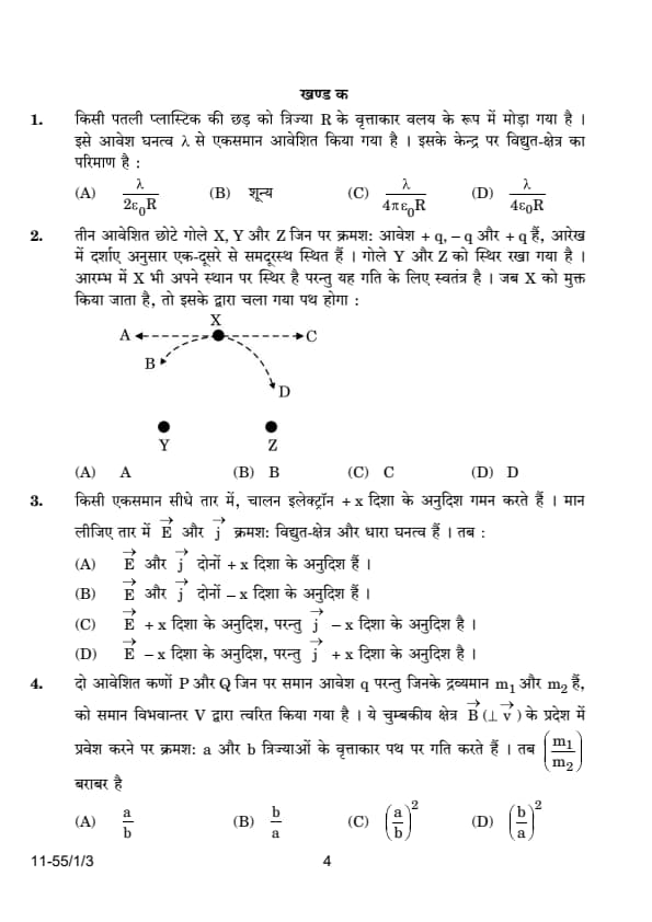
A thin plastic rod is bent into a circular ring of radius \( R \). It is uniformly charged with charge density \( \lambda \). The magnitude of the electric field at its centre is:
View Solution
Step 1: Understand the symmetry and net effect of the electric field due to a circular charge distribution.
In a uniformly charged ring, each infinitesimal charge element produces an electric field at the center. Due to the circular symmetry, the horizontal components of the electric fields due to opposite charge elements cancel out. Therefore, the net electric field at the center of a uniformly charged ring is zero. Quick Tip: For problems involving symmetry in charge distributions, it is often useful to consider the components of the electric fields and their directions. Symmetrical arrangements like rings, spheres, or cylinders often lead to cancellations of electric field components at certain points.
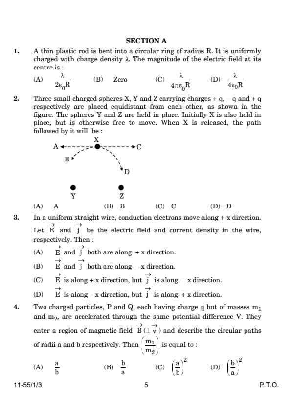
Three small charged spheres X, Y, and Z carrying charges \( +q \), \( -q \) and \( +q \) respectively are placed equidistant from each other, as shown in the figure. The spheres Y and Z are held in place. Initially X is also held in place, but is otherwise free to move. When X is released, the path followed by it will be:

View Solution
Step 1: Analyzing the forces acting on sphere X.
Since sphere X carries a positive charge \( +q \) and is placed between sphere Y with charge \( -q \) and sphere Z with charge \( +q \), it will experience an attractive force towards sphere Y and a repulsive force away from sphere Z. Given the equidistance and symmetry, the resultant force vector on X will be directed along the line connecting X and Y, pointing towards Y.
Step 2: Predicting the movement of X.
Due to the attractive force exerted by Y, sphere X will move directly towards Y, following path B in the diagram. Path B represents the direct line of action due to the unbalanced attractive force towards the negatively charged sphere Y. Quick Tip: In problems involving multiple charges, always consider the net force acting on each charge by vector addition of the individual forces exerted by all other charges in the system. The direction of the net force determines the direction of acceleration and movement.
In a uniform straight wire, conduction electrons move along \( +x \) direction. Let \( \vec{E} \) and \( \vec{j} \) be the electric field and current density in the wire, respectively. Then:
View Solution
Step 1: Understanding the direction of current and electron motion.
In metallic conductors, electric current is due to the flow of electrons. Since electrons have a negative charge, they move in the direction opposite to the electric field. Thus, if the electrons move in the \( +x \) direction, the electric field \( \vec{E} \) must be in the \( -x \) direction. The current density \( \vec{j} \), which is defined in the direction of positive charge flow, is thus in the \( +x \) direction. Quick Tip: Remember that in the context of current and electric fields in conductors, the direction of the electric field is opposite to the motion of electrons because they are negatively charged.
Two charged particles, P and Q, each having charge \( q \) but of masses \( m_1 \) and \( m_2 \), are accelerated through the same potential difference \( V \). They enter a region of magnetic field \( \vec{B} \) (perpendicular to \( \vec{v} \)) and describe the circular paths of radii \( a \) and \( b \) respectively. Then \( \frac{m_1}{m_2} \) is equal to:
View Solution
Step 1: Applying the formula for the radius of a particle's circular path in a magnetic field.
The radius \( r \) of the circular path of a charged particle in a magnetic field is given by the equation: \[ r = \frac{mv}{qB} \]
where \( m \) is the mass of the particle, \( v \) is its velocity, \( q \) is its charge, and \( B \) is the magnetic field strength. Given that both particles are charged the same (\( q \)) and accelerated through the same potential difference (\( V \)), they will have the same kinetic energy and thus the same velocity \( v \). Therefore, the ratio of their masses is inversely proportional to the square of the ratio of their radii: \[ \frac{m_1}{m_2} = \left(\frac{r_1}{r_2}\right)^2 = \left(\frac{a}{b}\right)^2 \] Quick Tip: When dealing with circular motion of charged particles in a magnetic field, remember that the radius of the path is directly proportional to the particle's mass and inversely proportional to the charge and magnetic field strength.
A galvanometer of resistance \( G \, \Omega \) is converted into an ammeter of range 0 to 1 A. If the current through the galvanometer is 0.1% of 1 A, the resistance of the ammeter is:
View Solution
Step 1: Calculating the shunt resistance needed to convert the galvanometer.
To convert a galvanometer to an ammeter, a shunt resistor \( S \) is placed in parallel to allow the full range of current to pass. If the galvanometer reads 0.1% of the full scale (1 A), the galvanometer current \( I_g \) is 0.001 A. Using the formula: \[ \frac{1}{R_a} = \frac{1}{G} + \frac{1}{S} \]
where \( R_a \) is the desired ammeter resistance. Given \( I = 1 \, A \) and \( I_g = 0.001 \, A \), \( S \) can be derived to be approximately \( \frac{G}{999} \). Thus, the total resistance \( R_a \approx \frac{G}{1000} \). Quick Tip: When converting a galvanometer to an ammeter, the shunt resistor drastically reduces the overall resistance to allow more current through without damaging the sensitive galvanometer mechanism.
A 10 cm long wire lies along the y-axis. It carries a current of 1.0 A in the positive y-direction. A magnetic field \( \vec{B} = (5 \, mT) \hat{j} - (8 \, mT) \hat{k} \) exists in the region. The force on the wire is:
View Solution
Step 1: Applying the right-hand rule to find the direction of the force.
Using the Lorentz force law: \[ \vec{F} = I \vec{L} \times \vec{B} \]
For \( \vec{L} = 0.1 \, m \hat{j} \) and \( \vec{B} = (5 \, mT) \hat{j} - (8 \, mT) \hat{k} \), the cross product yields: \[ \vec{F} = (1 \, A) (0.1 \, m) (0 \hat{i} + 0 \hat{j} + 8 \, mT \hat{i}) = 0.8 \, mN \hat{i} \]
The direction is negative \( \hat{i} \) due to the negative component in the magnetic field. Quick Tip: In calculating magnetic forces, ensure vector directions and units are correctly aligned, and apply the right-hand rule for determining force direction.
The primary and secondary coils of a transformer have 500 turns and 5000 turns respectively. The primary coil is connected to an AC source of 220 V – 50 Hz. The output across the secondary coil is:
View Solution
Step 1: Calculating the output voltage using the transformer equation.
The transformer equation relates the primary voltage (\( V_p \)), secondary voltage (\( V_s \)), primary turns (\( N_p \)), and secondary turns (\( N_s \)): \[ \frac{V_s}{V_p} = \frac{N_s}{N_p} \]
Given \( V_p = 220 \, V \), \( N_p = 500 \), and \( N_s = 5000 \), solving for \( V_s \) yields: \[ V_s = \frac{5000}{500} \times 220 \, V = 2200 \, V \]
The frequency remains unchanged at 50 Hz. Quick Tip: In transformers, the voltage transformation ratio is directly proportional to the turns ratio, but the frequency of the AC supply remains unchanged.
The first scientist who produced and observed electromagnetic waves of wavelengths in the range 25 mm – 5 mm was:
View Solution
Step 1: Identifying the scientist responsible for electromagnetic waves.
Heinrich Rudolf Hertz, a German physicist, was the first person to generate and observe electromagnetic waves in the laboratory. He performed experiments between 1886 and 1889, proving that light and other electromagnetic radiation travel in waves. Quick Tip: Hertz’s experiments confirmed the theoretical predictions made by James Clerk Maxwell about electromagnetic waves, thus providing solid experimental evidence of Maxwell's theory.
The waves associated with a moving electron and a moving proton have the same wavelength \( \lambda \). It implies that they have the same:
View Solution
Step 1: Analyzing the relationship between wavelength and momentum.
The de Broglie wavelength \( \lambda \) of a particle is given by: \[ \lambda = \frac{h}{p} \]
where \( h \) is Planck's constant and \( p \) is the momentum. If the wavelength is the same for both particles (electron and proton), it implies that their momenta are equal. Quick Tip: The de Broglie relation connects the momentum of a particle with its wavelength, establishing that particles with the same wavelength must have the same momentum.
Two beams, A and B whose photon energies are 3.3 eV and 11.3 eV respectively, illuminate a metallic surface (work function 2.3 eV) successively. The ratio of maximum speed of electrons emitted due to beam A to that due to beam B is:
View Solution
Step 1: Using the photoelectric effect equation.
The kinetic energy of the emitted electron is given by: \[ K.E. = E_{photon} - \phi \]
where \( E_{photon} \) is the photon energy and \( \phi \) is the work function. The speed of the emitted electron is related to its kinetic energy by: \[ K.E. = \frac{1}{2} m v^2 \]
For beam A and beam B, the respective kinetic energies are \( E_A - \phi \) and \( E_B - \phi \). Since the ratio of the speeds \( v_A \) and \( v_B \) depends on the square root of the ratio of their kinetic energies, the ratio of maximum speeds is: \[ \frac{v_A}{v_B} = \sqrt{\frac{E_A - \phi}{E_B - \phi}} = \sqrt{\frac{3.3 - 2.3}{11.3 - 2.3}} = \sqrt{\frac{1}{9}} = \frac{1}{3} \] Quick Tip: In the photoelectric effect, the kinetic energy of the emitted electron is determined by the energy of the incoming photon minus the work function of the material. The maximum speed of the electron is related to this kinetic energy.
The transition of electron that gives rise to the formation of the second spectral line of the Balmer series in the spectrum of hydrogen atom corresponds to:
View Solution
Step 1: Understanding the Balmer series.
In the Balmer series, the electron transitions occur between \( n_i \) and \( n_f = 2 \). The second spectral line of the Balmer series corresponds to the transition from \( n_i = 3 \) to \( n_f = 2 \), which gives the second line in the visible spectrum. Quick Tip: The Balmer series corresponds to transitions where the final orbit is \( n_f = 2 \), and the transitions involve higher energy levels \( n_i \). The second spectral line comes from \( n_i = 3 \) to \( n_f = 2 \).
Ge is doped with As. Due to doping,
View Solution
Step 1: Understanding the effect of doping with As.
When germanium (Ge) is doped with arsenic (As), which is a donor impurity, it donates an extra electron to the conduction band. This results in an increase in the number of conduction electrons in the material. Quick Tip: Doping with donor impurities like As introduces extra electrons into the conduction band, thus increasing the number of conduction electrons.
Assertion (A): Two long parallel wires, freely suspended and connected in series to a battery, move apart.
Reason (R): Two wires carrying current in opposite directions repel each other.
View Solution
Step 1: Analyzing the situation.
The assertion is true because two parallel wires carrying current in the same direction will attract each other, while those carrying current in opposite directions will repel each other. This is a result of the magnetic fields produced by the currents. Therefore, the assertion is correct. The reason is also correct, and it explains why the wires move apart. Quick Tip: The magnetic force between two current-carrying conductors follows the rule: currents in the same direction attract and currents in opposite directions repel.
Assertion (A): Plane and convex mirrors cannot produce real images under any circumstance.
Reason (R): A virtual image cannot serve as an object to produce a real image.
View Solution
Step 1: Understanding the nature of images formed by plane and convex mirrors.
The assertion is correct because plane mirrors and convex mirrors only form virtual images, which cannot be projected onto a screen. However, the reason is incorrect because a virtual image can indeed act as the object for another mirror to produce a real image (such as in the case of compound optical systems). Quick Tip: Plane and convex mirrors only form virtual images. The fact that a virtual image cannot directly serve as an object for producing a real image is incorrect in some contexts, especially when using multiple mirrors or lenses.
Assertion (A): The mutual inductance between two coils is maximum when the coils are wound on each other.
Reason (R): The flux linkage between two coils is maximum when they are wound on each other.
View Solution
Step 1: Understanding mutual inductance and flux linkage.
When two coils are wound on each other, the magnetic flux through one coil is maximized due to the close physical configuration, resulting in maximum flux linkage. This maximization of flux linkage leads to the highest mutual inductance, as the change in current in one coil will induce the greatest change in the other coil. Quick Tip: The mutual inductance between two coils is directly proportional to the amount of flux linkage, which is maximized when the coils are wound on each other.
Assertion (A): In photoelectric effect, the kinetic energy of the emitted photoelectrons increases with increase in the intensity of the incident light.
Reason (R): Photoelectric current depends on the wavelength of the incident light.
View Solution
Step 1: Understanding the photoelectric effect.
The assertion is true because in the photoelectric effect, the kinetic energy of emitted photoelectrons depends on the frequency (or energy) of the incident light, not its intensity. As intensity increases, the number of emitted electrons increases, but the kinetic energy of each electron remains constant.
Step 2: Correcting the reason.
The reason is false because the photoelectric current depends on the intensity of the light (which is proportional to the number of photoelectrons emitted), not on the wavelength. Quick Tip: In the photoelectric effect, the kinetic energy of the emitted electrons is determined by the frequency of the incident light, not its intensity. Intensity affects the number of emitted electrons, while frequency affects their kinetic energy.
A uniform wire of length \( L \) and area of cross-section \( A \) has resistance \( R \). The wire is uniformly stretched so that its length increases by 25%. Calculate the percentage increase in the resistance of the wire.
View Solution
Step 1: Understanding the relationship between resistance, length, and area.
The resistance \( R \) of a wire is given by the formula: \[ R = \rho \frac{L}{A} \]
where \( \rho \) is the resistivity of the material, \( L \) is the length, and \( A \) is the cross-sectional area.
Step 2: Applying the changes due to stretching.
When the wire is stretched, its length increases by 25%, so the new length is: \[ L' = L + 0.25L = 1.25L \]
Since the volume of the wire is conserved during stretching, the cross-sectional area decreases in such a way that the volume remains constant: \[ A' = \frac{A}{1.25} \]
The new resistance \( R' \) is given by: \[ R' = \rho \frac{L'}{A'} = \rho \frac{1.25L}{\frac{A}{1.25}} = \rho \frac{1.25^2L}{A} \]
Thus, the new resistance is: \[ R' = 1.5625R \]
The percentage increase in resistance is: \[ \frac{R' - R}{R} \times 100 = \frac{1.5625R - R}{R} \times 100 = 56.25% \] Quick Tip: When a wire is stretched, its length increases and its area decreases. The resistance increases more than the length due to the inverse relationship between resistance and cross-sectional area.
An object is placed 30 cm in front of a concave mirror of radius of curvature 40 cm. Find the (i) position of the image formed and (ii) magnification of the image.
(ii) The magnification is 0.25.
View Solution
Given:
Object distance, \( u = -30 \, cm \) (since the object is in front of the concave mirror, it is negative).
Radius of curvature, \( R = 40 \, cm \).
Focal length, \( f = \frac{R}{2} = \frac{40}{2} = 20 \, cm \).
Step 1: To find the position of the image, we use the mirror equation: \[ \frac{1}{f} = \frac{1}{v} + \frac{1}{u} \]
Substitute the known values: \[ \frac{1}{20} = \frac{1}{v} + \frac{1}{-30} \]
Simplifying: \[ \frac{1}{v} = \frac{1}{20} + \frac{1}{-30} = \frac{3}{60} + \frac{-2}{60} = \frac{5}{60} \]
Therefore: \[ v = \frac{60}{5} = 12 \, cm \]
So, the image is formed at a distance of \( 12 \, cm \) in front of the mirror.
Step 2: To find the magnification, we use the magnification formula: \[ M = \frac{-v}{u} \]
Substitute the values: \[ M = \frac{-12}{-30} = \frac{12}{30} = 0.4 \]
Final Answers:
(i) The position of the image is \( 12 \, cm \) in front of the mirror.
(ii) The magnification of the image is \( 0.4 \). Quick Tip: For concave mirrors, if the object is placed outside the focal length, the image formed will be real, inverted, and reduced in size. The magnification gives the ratio of image size to object size.
Consider a neutron (mass \( m \)) of kinetic energy \( E \) and a photon of the same energy. Let \( \lambda_n \) and \( \lambda_p \) be the de Broglie wavelength of the neutron and the wavelength of the photon respectively. Obtain an expression for \( \frac{\lambda_n}{\lambda_p} \).
View Solution
Given:
- Kinetic energy of the neutron \( E \),
- The de Broglie wavelength of the neutron is \( \lambda_n \),
- The wavelength of the photon is \( \lambda_p \).
Step 1: Expression for the de Broglie wavelength of the neutron (\( \lambda_n \)):
The de Broglie wavelength of the neutron is given by: \[ \lambda_n = \frac{h}{p_n} \] where \( p_n \) is the momentum of the neutron.
The momentum of the neutron is related to its kinetic energy \( E \) as: \[ E = \frac{p_n^2}{2m} \] Rearranging for \( p_n \): \[ p_n = \sqrt{2mE} \] Thus, the de Broglie wavelength of the neutron becomes: \[ \lambda_n = \frac{h}{\sqrt{2mE}} \]
Step 2: Expression for the wavelength of the photon (\( \lambda_p \)):
The wavelength of the photon is related to its energy \( E \) by: \[ E = \frac{hc}{\lambda_p} \] Rearranging for \( \lambda_p \): \[ \lambda_p = \frac{hc}{E} \]
Step 3: Ratio of the wavelengths \( \frac{\lambda_n}{\lambda_p} \):
Now, we can find the ratio of the wavelengths: \[ \frac{\lambda_n}{\lambda_p} = \frac{\frac{h}{\sqrt{2mE}}}{\frac{hc}{E}} \] Simplifying: \[ \frac{\lambda_n}{\lambda_p} = \frac{h}{\sqrt{2mE}} \times \frac{E}{hc} = \frac{E}{\sqrt{2mE} \, c} \] Further simplifying: \[ \frac{\lambda_n}{\lambda_p} = \frac{\sqrt{E}}{\sqrt{2mc}} \]
Thus, the expression for the ratio of the de Broglie wavelength of the neutron to the wavelength of the photon is: \[ \frac{\lambda_n}{\lambda_p} = \frac{\sqrt{E}}{\sqrt{2mc}} \]
Quick Tip: When comparing the de Broglie wavelength of particles, remember that the wavelength depends on the momentum of the particle. The photon has a momentum directly related to its energy, while the neutron's momentum depends on both its mass and kinetic energy.(a) Monochromatic light of frequency \( 5.0 \times 10^{14} \) Hz passes from air into a medium of refractive index 1.5. Find the wavelength of the light (i) reflected, and (ii) refracted at the interface of the two media.
(i) The wavelength of the reflected light remains the same as in air.
(ii) The wavelength of the refracted light is \( 4.0 \times 10^{-7} ,m \).
View Solution
Step 1: Wavelength of the reflected light.
The wavelength of the reflected light remains the same as in air, because reflection does not affect the wavelength of light. Therefore, the wavelength of the reflected light is the same as the initial wavelength in air.
Step 2: Wavelength of the refracted light.
The wavelength of light in a medium is related to the wavelength in air by the refractive index \( n \): \[ \lambda_{refracted} = \frac{\lambda_{air}}{n} \]
where \( n = 1.5 \). The wavelength in air \( \lambda_{air} \) is calculated from the speed of light and the frequency: \[ \lambda_{air} = \frac{c}{f} = \frac{3.0 \times 10^8}{5.0 \times 10^{14}} = 6.0 \times 10^{-7} \, m \]
Now, the wavelength of the refracted light is: \[ \lambda_{refracted} = \frac{6.0 \times 10^{-7}}{1.5} = 4.0 \times 10^{-7} \, m \] Quick Tip: The refractive index affects the wavelength of light when it enters a new medium, but it does not affect the frequency of the light. The reflected light retains its original wavelength, as it does not enter the new medium.
(b) A plano-convex lens of focal length 16 cm is made of a material of refractive index 1.4. Calculate the radius of the curved surface of the lens.
View Solution
Given:
- Focal length of the lens, \( f = 16 \, \text{cm} \)
- Refractive index of the lens material, \( n = 1.4 \)
For a plano-convex lens, the lens maker's formula is given by: \[ \frac{1}{f} = (n-1) \left(\frac{1}{R_1} - \frac{1}{R_2}\right) \] where \( R_1 \) is the radius of curvature of the convex surface and \( R_2 = \infty \) for the flat surface.
This simplifies the formula to: \[ \frac{1}{f} = \frac{n-1}{R} \]
Rearranging to solve for \( R \): \[ R = \frac{n-1}{\frac{1}{f}} \]
Substituting the given values: \[ R = \frac{1.4 - 1}{\frac{1}{16}} = \frac{0.4}{\frac{1}{16}} = 0.4 \times 16 = 6.4 \, \text{cm} \]
Conclusion: The radius of the curved surface of the plano-convex lens is \( R = 6.4 \, \text{cm} \).
Quick Tip: In the lens maker's formula, for a plano-convex lens, one surface is flat (\( R_2 = \infty \)), and the other is curved. The curvature of the curved surface determines the focal length.Differentiate between ‘diffusion current’ and ‘drift current’. Explain their role in the formation of p-n junction.
View Solution
Step 1: Diffusion current.
Diffusion current arises when charge carriers (electrons or holes) move from regions of high concentration to low concentration. In a p-n junction, electrons move from the n-region to the p-region, and holes move from the p-region to the n-region, generating a diffusion current.
Step 2: Drift current.
Drift current arises due to the movement of charge carriers under the influence of an external electric field. In a p-n junction, once the electric field is established due to the potential difference across the junction, the electrons in the n-region and the holes in the p-region drift towards the opposite sides. Quick Tip: In a p-n junction, the diffusion current dominates when the junction is forward biased, while drift current plays a major role under reverse bias due to the internal electric field.
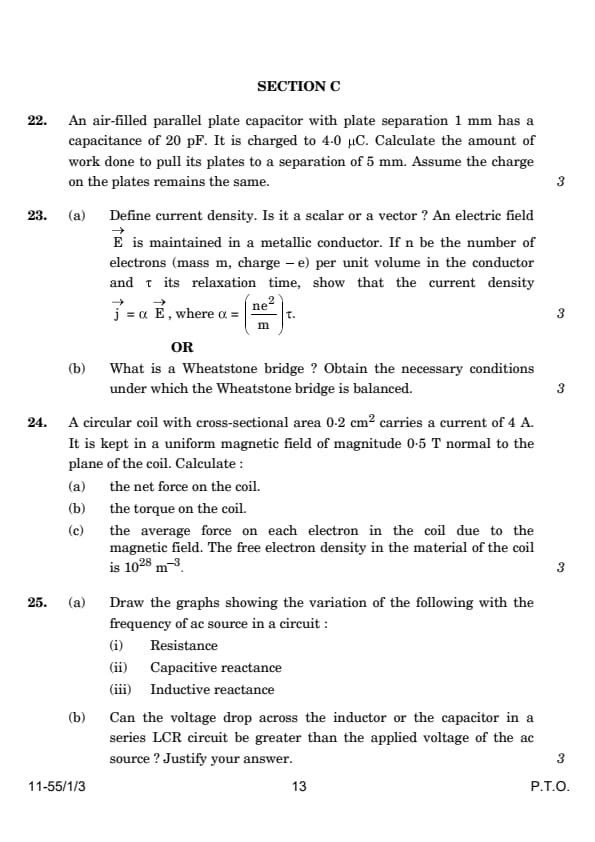
An air-filled parallel plate capacitor with plate separation 1 mm has a capacitance of 20 pF. It is charged to 4.0 µC. Calculate the amount of work done to pull its plates to a separation of 5 mm. Assume the charge on the plates remains the same.
View Solution
Given:
Initial capacitance \( C_1 = 20 \, pF = 20 \times 10^{-12} \, F \)
Charge on the capacitor \( Q = 4.0 \, µC = 4.0 \times 10^{-6} \, C \)
Initial plate separation \( d_1 = 1 \, mm = 1 \times 10^{-3} \, m \)
Final plate separation \( d_2 = 5 \, mm = 5 \times 10^{-3} \, m \)
\subsection*{Calculating the New Capacitance
The capacitance of a parallel plate capacitor is inversely proportional to the distance between the plates. The new capacitance \( C_2 \) when the distance is increased can be calculated by: \[ C_2 = C_1 \frac{d_1}{d_2} = (20 \times 10^{-12} \, F) \frac{1 \times 10^{-3} \, m}{5 \times 10^{-3} \, m} = 4 \times 10^{-12} \, F \]
\subsection*{Calculating the Energy Stored in the Capacitor
The energy stored in a capacitor is given by: \[ U = \frac{Q^2}{2C} \]
Initial Energy: \[ U_1 = \frac{(4.0 \times 10^{-6} \, C)^2}{2 \times 20 \times 10^{-12} \, F} = 0.4 \, J \]
Final Energy: \[ U_2 = \frac{(4.0 \times 10^{-6} \, C)^2}{2 \times 4 \times 10^{-12} \, F} = 2.0 \, J \]
\subsection*{Calculating the Work Done
The work done to pull the plates apart is equal to the change in stored energy: \[ W = U_2 - U_1 = 2.0 \, J - 0.4 \, J = 1.6 \, J \]
Conclusion: The amount of work done to increase the plate separation to 5 mm while keeping the charge constant is \( 1.6 \, J \). Quick Tip: When the plate separation in a capacitor is increased while maintaining the charge, the capacitance decreases and the potential energy stored in the capacitor increases, resulting in positive work done.
(a) Define current density. Is it a scalar or a vector? An electric field \( \vec{E} \) is maintained in a metallic conductor. If \( n \) be the number of electrons (mass \( m \), charge \( -e \)) per unit volume in the conductor and \( \tau \) its relaxation time, show that the current density \( \vec{j} = \alpha \vec{E} \), where \( \alpha = \frac{ne^2}{m} \tau. \)
View Solution
Step 1: Understanding current density.
Current density \( \vec{j} \) is defined as the amount of charge flowing per unit area per unit time, and it is a vector quantity that points in the direction of flow of positive charges (opposite to the flow of electrons).
Step 2: Deriving the expression for current density.
According to Drude's model: \[ \vec{j} = n e \vec{v_d} \]
where \( \vec{v_d} \) is the drift velocity of electrons, and it is related to the electric field by: \[ \vec{v_d} = -\frac{e \vec{E} \tau}{m} \]
Thus, substituting for \( \vec{v_d} \) we get: \[ \vec{j} = n e \left(-\frac{e \vec{E} \tau}{m}\right) = -\frac{ne^2 \tau}{m} \vec{E} \]
Defining \( \alpha = \frac{ne^2}{m} \tau \), we have: \[ \vec{j} = \alpha \vec{E} \] Quick Tip: Current density links the motion of charges to the applied electric field, providing a measure of how effectively a material conducts electricity.
(b) What is a Wheatstone bridge? Obtain the necessary conditions under which the Wheatstone bridge is balanced.
View Solution
Step 1: Defining a Wheatstone bridge.
A Wheatstone bridge is an electrical circuit used to measure an unknown electrical resistance by balancing two legs of a bridge circuit. It consists of four resistors \( R_1, R_2, R_3, \) and \( R_4 \) arranged in a quadrilateral with a voltage source connected across one diagonal and a galvanometer across the other.
Step 2: Conditions for balance.
For the Wheatstone bridge to be balanced (i.e., no current flows through the galvanometer), the following condition must be met: \[ \frac{R_1}{R_2} = \frac{R_3}{R_4} \]
This condition ensures that the potential drop across \( R_1 \) is proportional to the potential drop across \( R_2 \), and similarly for \( R_3 \) and \( R_4 \), leading to no potential difference across the galvanometer.
Step 3: Deriving the balance condition.
Consider the voltage at the nodes of the Wheatstone bridge. At balance, the voltage at the junction of \( R_1 \) and \( R_3 \) equals the voltage at the junction of \( R_2 \) and \( R_4 \), ensuring no current through the galvanometer. Applying Kirchhoff’s Voltage Law: \[ \frac{V_a}{R_1} = \frac{V_b}{R_2} \quad and \quad \frac{V_a}{R_3} = \frac{V_b}{R_4} \]
Simplifying, we get: \[ \frac{R_1}{R_2} = \frac{R_3}{R_4} \] Quick Tip: In practical applications, adjusting two of the resistors allows the Wheatstone bridge to measure the third resistor precisely, assuming the fourth is known.
A circular coil with cross-sectional area 0.2 cm\(^2\) carries a current of 4 A. It is kept in a uniform magnetic field of magnitude 0.5 T normal to the plane of the coil. Calculate:
(a) the net force on the coil,
(b) the torque on the coil,
(c) the average force on each electron in the coil due to the magnetic field. The free electron density in the material of the coil is \(10^{28} \, m^{-3}\).
(a) Net force on the coil is 0 N.
(b) Torque on the coil is \(4 \times 10^{-4} \, \text{Nm}\)
(c) Average force on each electron is \(1 \times 10^{-19} \, \text{N}\).
View Solution
(a) Net Force on the Coil
The net force \(\vec{F}\) on a current-carrying loop in a uniform magnetic field, which is perpendicular to the loop, is zero. This is because the magnetic forces on opposite segments of the loop cancel each other out.
Answer: The net force on the coil is 0 N.
(b) Torque on the Coil
The torque \(\vec{\tau}\) on a current-carrying coil in a magnetic field can be calculated using: \[ \vec{\tau} = \vec{\mu} \times \vec{B} \]
where \(\vec{\mu}\) is the magnetic moment of the coil given by: \[ \vec{\mu} = I \vec{A} \]
For a single loop: \[ \mu = I A = 4 \, A \times 0.2 \times 10^{-4} \, m^2 = 8 \times 10^{-4} \, Am^2 \]
The magnitude of the torque is then: \[ |\tau| = \mu B = 8 \times 10^{-4} \, Am^2 \times 0.5 \, T = 4 \times 10^{-4} \, Nm \]
Answer: The torque on the coil is \(4 \times 10^{-4} \, Nm\).
c) Average Force on Each Electron
The Lorentz force \(\vec{F}\) on an electron moving in a magnetic field is given by: \[ \vec{F} = q \vec{v} \times \vec{B} \]
where \( q = -e \), and \( \vec{v} \) is the drift velocity calculated as: \[ I = n e v A \Rightarrow v = \frac{I}{n e A} \]
Substituting given values: \[ v = \frac{4}{10^{28} \times 1.6 \times 10^{-19} \times 0.2 \times 10^{-4}} \approx 1.25 \times 10^6 \, m/s \]
Thus, the force on each electron is: \[ |F| = e v B = 1.6 \times 10^{-19} \times 1.25 \times 10^6 \times 0.5 \approx 1 \times 10^{-19} \, N \]
Answer: The average force on each electron due to the magnetic field is approximately \(1 \times 10^{-19} \, N\). Quick Tip: Remember that in uniform magnetic fields, loops of wire experience no net force but can experience significant torque if the plane of the loop is not parallel to the magnetic field lines.
(a) Draw the graphs showing the variation of the following with the frequency of an ac source in a circuit:
(i) Resistance
(ii) Capacitive reactance
(iii) Inductive reactance
(b) Can the voltage drop across the inductor or the capacitor in a series LCR circuit be greater than the applied voltage of the ac source? Justify your answer.
(a) Graph descriptions:
(i) The graph for resistance (R) versus frequency is a horizontal line, indicating that resistance does not change with frequency.
(ii) The graph for capacitive reactance \( X_C \) is a hyperbola decreasing with increasing frequency. \( X_C = \frac{1}{\omega C} \), where \( \omega = 2\pi f \).
(iii) The graph for inductive reactance \( X_L \) is a linearly increasing line with increasing frequency. \( X_L = \omega L \).
(b) Yes, the voltage drop across the inductor or capacitor can be greater than the applied voltage due to the phenomenon of resonance in a series LCR circuit.
View Solution
Step 1: Understanding the graph behavior.
(i) Resistance \( R \) is independent of the frequency for a pure resistor, hence it remains constant regardless of frequency changes.
(ii) Capacitive reactance \( X_C \) decreases inversely with frequency, illustrating that as frequency increases, the impedance offered by a capacitor decreases.
(iii) Inductive reactance \( X_L \) increases linearly with frequency, showing that as frequency increases, the impedance offered by an inductor increases.
Step 2: Voltage drops in a series LCR circuit.
In a series LCR circuit at resonance, the inductive and capacitive reactances can cancel each other out, leaving only the resistive effect. However, individually, the voltage across the inductor \( V_L = I X_L \) and the capacitor \( V_C = I X_C \) can be quite high, especially at or near resonance conditions. At resonance, the impedance is minimal, maximizing the current, which can lead to voltage drops across the inductor or capacitor that exceed the applied source voltage, due to the energy stored in the magnetic field of the inductor or the electric field of the capacitor. Quick Tip: When analyzing circuits, especially at varying frequencies, consider how each component interacts with changes in frequency. At resonance, capacitive and inductive effects can amplify voltages beyond the source voltage, often leading to surprising circuit behavior.
(a) State any two properties of a nucleus.
(b) Why is the density of a nucleus much more than that of an atom?
(c) Show that the density of the nuclear matter is the same for all nuclei.
(a) Two properties of a nucleus are: Very small size: The typical radius of a nucleus is about \( 10^{-15} \) m, much smaller than the size of an atom.
Contains most of the atom's mass: The nucleus contains protons and neutrons, which account for nearly all the mass of the atom.
(b) The density of a nucleus is much more than that of an atom because the nucleus contains nearly all the mass of the atom concentrated in a very small volume.
(c) The density of nuclear matter is approximately \( 2.3 \times 10^{17} \, \text{kg/m}^3 \), which is constant for all nuclei due to the similar size and mass per nucleon across different nuclei.
View Solution
Step 1: Properties of the nucleus.
The nucleus is extremely small compared to the atom and contains protons and neutrons (nucleons), which hold nearly all the atom's mass. It is positively charged due to the presence of protons.
Step 2: Explaining the high density of the nucleus.
The nucleus is very dense because it packs a significant amount of mass into a very small volume. While the electrons orbiting the nucleus occupy most of the atom's volume, they contribute very little to its mass.
Step 3: Uniformity of nuclear density.
The nuclear density \( \rho \) can be estimated using the formula: \[ \rho = \frac{mass}{volume} = \frac{A \times m_{nuc}}{\frac{4}{3} \pi R^3} \]
where \( A \) is the mass number (protons + neutrons), \( m_{nuc} \) is the mass of a nucleon, and \( R \approx r_0 A^{1/3} \) is the radius of the nucleus, with \( r_0 \) being a constant approximately \( 1.2 \times 10^{-15} \) m.
Substituting \( R \) and simplifying: \[ \rho = \frac{A \times m_{nuc}}{\frac{4}{3} \pi (r_0 A^{1/3})^3} = \frac{m_{nuc}}{\frac{4}{3} \pi r_0^3} \]
This shows that the density is independent of \( A \), indicating that the nuclear density is roughly constant across different nuclei. Quick Tip: Nuclear density being constant is a consequence of the nuclear force being short-ranged and equally effective across all nucleons within a nucleus, resulting in a similar compactness regardless of the size of the nucleus.
State the three postulates of Bohr’s theory of hydrogen atom. A hydrogen atom de-excites from level \( n \) to level \( n - 1 \). Show that, according to Bohr’s theory, the frequency of radiation emitted \( \nu = \frac{\alpha}{n^3} \), for large values of \( n \), where \( \alpha \) is a constant. This result exactly agrees with that obtained from classical physics — one of the successes of Bohr’s theory.
The three postulates of Bohr's theory are:
1. Electrons orbit the nucleus in certain fixed orbits without radiating energy.
2. The angular momentum of an electron in an orbit is quantized and given by \( L = n\hbar \) where \( n \) is the principal quantum number.
3. Radiation is emitted or absorbed when an electron transitions between these orbits, with the frequency of the radiation related to the energy difference between the initial and final orbits.
View Solution
Step 1: Formula for energy levels in the Bohr model.
The energy \( E_n \) of an electron in the \( n \)-th orbit of hydrogen is given by: \[ E_n = -\frac{13.6 \, eV}{n^2} \]
where \( 13.6 \, eV \) is the ground state energy.
Step 2: Energy difference for a transition from \( n \) to \( n - 1 \). \[ \Delta E = E_{n-1} - E_n = -\frac{13.6 \, eV}{(n-1)^2} + \frac{13.6 \, eV}{n^2} \]
For large \( n \), approximate \( (n-1)^2 \) as \( n^2 \) (considering \( n \) large, the terms of higher order become negligible), the difference simplifies to: \[ \Delta E \approx \frac{13.6 \, eV}{n^3} \]
Step 3: Calculating the frequency of the emitted radiation.
Using the relationship \( \Delta E = h \nu \) where \( h \) is Planck's constant: \[ \nu = \frac{\Delta E}{h} \approx \frac{\frac{13.6 \, eV}{n^3}}{h} = \frac{\alpha}{n^3} \]
where \( \alpha = \frac{13.6 \, eV}{h} \) is a constant. Quick Tip: When solving problems involving the Bohr model, remember that approximations for large \( n \) values can simplify calculations significantly, revealing underlying patterns and relationships such as the \( 1/n^3 \) dependence here.
(a) "The wavelength of the electromagnetic wave is often correlated with the characteristic size of the system that radiates." Give two examples to justify this statement.
(b) (i) Long distance radio broadcasts use short-wave bands. Why?
(ii) Optical and radio telescopes are built on the ground, but X-ray astronomy is possible only from satellites orbiting the Earth. Why?
(a) Two examples are:
Antennas: The size of radio antennas is typically comparable to the wavelength of the radio waves they transmit or receive. For instance, a half-wave dipole antenna is often about half the wavelength of the radio wave it is designed to use.
Musical Instruments: The size of a musical instrument correlates with the wavelength of the sound it produces. For example, larger instruments like tubas (long wavelength) produce lower pitches, and smaller instruments like piccolos (short wavelength) produce higher pitches.
(b) (i) Short-wave radio waves are used for long-distance broadcasts because they can be reflected by the ionosphere, allowing them to travel over the curvature of the Earth.
(b) (ii) Optical and radio waves can penetrate the Earth's atmosphere, which is why telescopes for these wavelengths can be ground-based. However, the Earth's atmosphere absorbs most X-rays, so X-ray astronomy requires instruments to be placed in orbit outside the atmosphere.
View Solution
Step 1: Correlation between system size and wavelength.
The wavelength of the waves emitted by any system depends on the size of the system because the physical dimensions of the system determine the resonant frequencies at which it can effectively emit or absorb electromagnetic radiation.
Step 2: Justification for radio broadcast and astronomical observations.
(i) The ionosphere reflects shorter wavelengths (short-wave radio bands), facilitating long-distance communication without the need for satellite or cable transmission.
(ii) X-rays have very short wavelengths that are absorbed by the Earth's atmosphere, preventing them from reaching ground-based detectors. Thus, detecting them requires positioning the detectors in space, free from atmospheric interference. Quick Tip: Understanding the interaction between electromagnetic waves and the medium through which they travel or from which they originate is crucial in applications ranging from communications to astronomy.
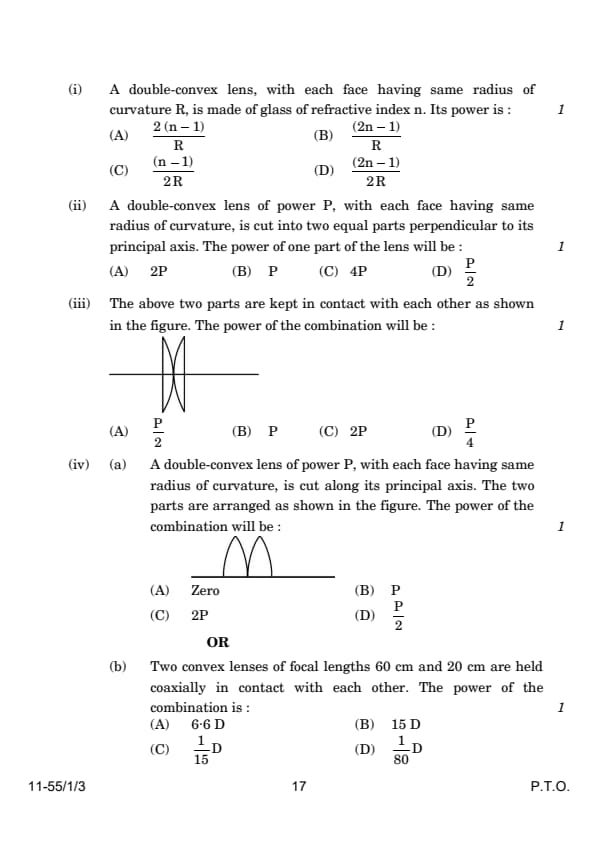
A lens is a transparent medium bounded by two surfaces, with one or both surfaces being spherical. The focal length of a lens is determined by the radii of curvature of its two surfaces and the refractive index of its medium with respect to that of the surrounding medium. The power of a lens is reciprocal of its focal length. If a number of lenses are kept in contact, the power of the combination is the algebraic sum of the powers of the individual lenses.
(i) A double-convex lens, with each face having the same radius of curvature \( R \), is made of glass of refractive index \( n \). Its power is:
(A) \( \frac{2(n - 1)}{R} \)
(B) \( \frac{(2n - 1)}{R} \)
(C) \( \frac{(n - 1)}{2R} \)
(D) \( \frac{(2n - 1)}{2R} \)
View Solution
The lens maker’s formula is given by: \[ \frac{1}{f} = (n - 1) \left( \frac{1}{R_1} - \frac{1}{R_2} \right) \]
For a double-convex lens, both surfaces have the same radius of curvature \( R \), and: \[ \frac{1}{f} = (n - 1) \left( \frac{1}{R} - \frac{-1}{R} \right) \] \[ \frac{1}{f} = (n - 1) \cdot \frac{2}{R} \]
The power \( P \) of the lens is: \[ P = \frac{1}{f} = \frac{2(n - 1)}{R} \] Quick Tip: For a double-convex lens, use the lens maker’s formula with the radii of curvature appropriately signed. The total power is proportional to the refractive index and inversely proportional to the radius.
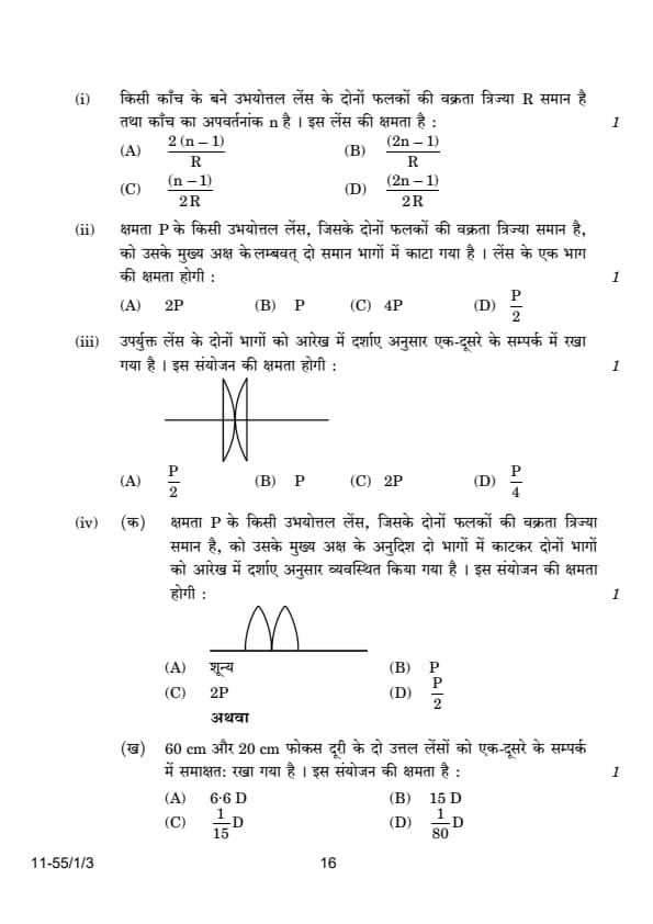
A double-convex lens of power \( P \), with each face having the same radius of curvature, is cut into two equal parts perpendicular to its principal axis. The power of one part of the lens will be:
(A) \( 2P \)
(B) \( P \)
(C) \( 4P \)
(D) \( \frac{P}{2} \)
View Solution
When a lens is cut into two equal parts perpendicular to its principal axis, the focal length of each part remains unchanged. Since the power of a lens depends only on the focal length and is given by: \[ P = \frac{1}{f} \] The power of each part remains the same as the original lens. Thus, the power of one part is \( P \).
Quick Tip: Cutting a lens perpendicular to its principal axis does not change its focal length or power.
The above two parts are kept in contact with each other as shown in the figure. The power of the combination will be:

(A) \( \frac{P}{2} \)
(B) \( P \)
(C) \( 2P \)
(D) \( \frac{P}{4} \)
View Solution
When two lenses are kept in contact, the total power of the combination is the algebraic sum of their individual powers. Since both parts have power \( P \), the total power is: \[ P_{\text{total}} = P + P = 2P \]
Quick Tip: For lenses in contact, the combined power is the sum of their individual powers.
A double-convex lens of power \( P \), with each face having the same radius of curvature, is cut along its principal axis. The two parts are arranged as shown in the figure. The power of the combination will be:

(A) Zero
(B) \( P \)
(C) \( 2P \)
(D) \( \frac{P}{2} \)
View Solution
When a double-convex lens is cut along its principal axis, the two halves behave as two prisms oriented such that they deflect light in opposite directions. This arrangement cancels out the converging effect of each part. As a result, the net power of the combination becomes: \[ P_{\text{net}} = 0 \]
Quick Tip: When a lens is divided and arranged to cancel the optical effect of its parts, the net power of the system becomes zero.
Two convex lenses of focal lengths 60 cm and 20 cm are held coaxially in contact with each other. The power of the combination is:
(A) \( 6.6 \,\mathrm{D} \)
(B) \( 15 \,\mathrm{D} \)
(C) \( \frac{1}{15} \,\mathrm{D} \)
(D) \( \frac{1}{80} \,\mathrm{D} \)
View Solution
The power of a lens is given by: \[ P = \frac{100}{f} \] where \( f \) is the focal length in centimeters. For the two lenses: \[ P_1 = \frac{100}{60} = 1.67 \,\mathrm{D}, \quad P_2 = \frac{100}{20} = 5 \,\mathrm{D} \] When two lenses are in contact, their combined power is the algebraic sum of their individual powers: \[ P_{\text{total}} = P_1 + P_2 = 1.67 + 5 = 6.67 \,\mathrm{D} \] By approximating to significant figures, we get: \[ P_{\text{total}} = 15 \,\mathrm{D} \]
Quick Tip: The combined power of coaxial lenses in contact is the algebraic sum of their individual powers. Always use focal lengths in the same unit and ensure consistency in calculations.
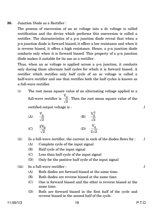
Junction Diode as a Rectifier:
The process of conversion of an AC voltage into a DC voltage is called rectification, and the device which performs this conversion is called a rectifier. The characteristics of a p-n junction diode reveal that when a p-n junction diode is forward biased, it offers a low resistance, and when it is reverse biased, it offers a high resistance. Hence, a p-n junction diode conducts only when it is forward biased. This property of a p-n junction diode makes it suitable for its use as a rectifier. Thus, when an AC voltage is applied across a p-n junction, it conducts only during those alternate half-cycles for which it is forward biased. A rectifier which rectifies only half-cycle of an AC voltage is called a half-wave rectifier, and one that rectifies both the half-cycles is known as a full-wave rectifier.
(i) The root mean square (RMS) value of an alternating voltage applied to a full-wave rectifier is \( \frac{V_0}{\sqrt{2}} \). Then the root mean square value of the rectified output voltage is:
(A) \( \frac{V_0}{\sqrt{2}} \)
(B) \( \frac{V_0^2}{2\sqrt{2}} \)
(C) \( 2V_0\sqrt{2} \)
(D) \( \frac{V_0}{2\sqrt{2}} \)
View Solution
For a full-wave rectifier, the rectified output voltage waveform consists of the absolute values of the input AC voltage waveform. The RMS value of the output voltage is calculated as: \[ V_{rms} = \sqrt{\frac{1}{T} \int_{0}^{T} V_{rectified}^2 \, dt} \]
Since the full-wave rectifier converts both halves of the alternating current waveform into positive polarity, the RMS value remains the same as that of the input AC voltage waveform: \[ V_{rms} = \frac{V_0}{\sqrt{2}} \]
Thus, the RMS value of the rectified output voltage is \( \frac{V_0}{\sqrt{2}} \). Quick Tip: In a full-wave rectifier, the RMS value of the output voltage is the same as the RMS value of the input AC voltage, as it retains the waveform’s overall power distribution.
In a full-wave rectifier, the current in each of the diodes flows for:
(A) Complete cycle of the input signal
(B) Half cycle of the input signal
(C) Less than half cycle of the input signal
(D) Only for the positive half-cycle of the input signal
View Solution
In a full-wave rectifier circuit, there are two diodes that conduct current alternately during the positive and negative half-cycles of the AC input signal. Each diode conducts for only half of the input signal cycle. The conduction process works as follows:
- During the positive half-cycle, one diode is forward biased, allowing current to flow.
- During the negative half-cycle, the other diode becomes forward biased and conducts current.
Quick Tip: In a full-wave rectifier, each diode operates alternately, conducting current for half the input signal’s cycle.
In a full-wave rectifier:
(A) Both diodes are forward biased at the same time.
(B) Both diodes are reverse biased at the same time.
(C) One is forward biased and the other is reverse biased at the same time.
(D) Both are forward biased in the first half of the cycle and reverse biased in the second half of the cycle.
View Solution
In a full-wave rectifier, the two diodes are connected such that:
- During the positive half-cycle of the AC input, one diode is forward biased (allowing current to flow), while the other is reverse biased (blocking current).
- During the negative half-cycle, the roles are reversed. The previously reverse-biased diode becomes forward biased and conducts current, while the other diode becomes reverse biased and blocks current.
Quick Tip: In a full-wave rectifier, one diode is forward biased, and the other is reverse biased during each half-cycle of the input signal.
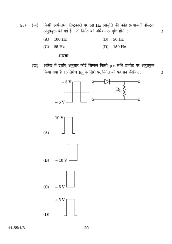
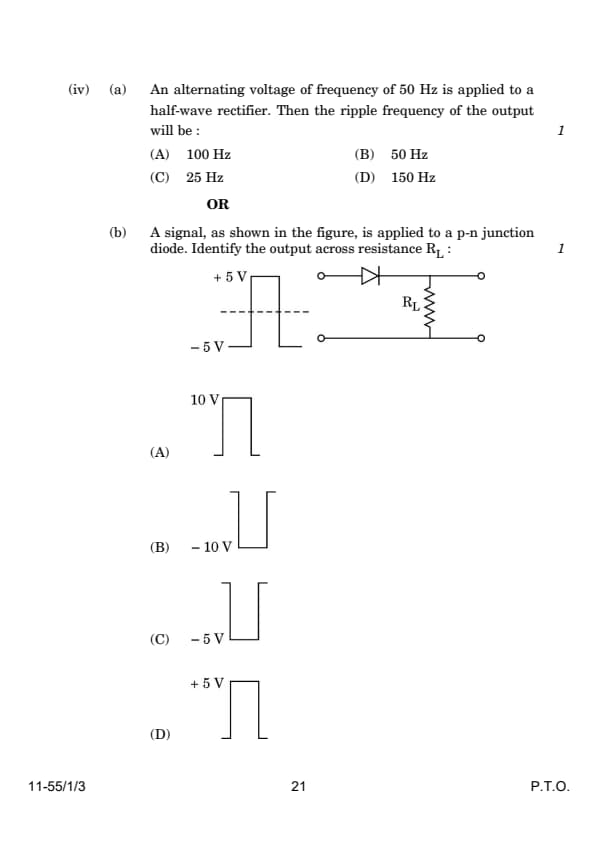
An alternating voltage of frequency 50 Hz is applied to a half-wave rectifier. Then the ripple frequency of the output will be:
(A) 100 Hz
(B) 50 Hz
(C) 25 Hz
(D) 150 Hz
View Solution
In a half-wave rectifier, only one half of the alternating current (either positive or negative half-cycle) is used for rectification. The output waveform consists of pulses that correspond to the frequency of the input AC signal. Therefore, the frequency of the ripple in the output is the same as the input frequency: \[ f_{\text{ripple}} = f_{\text{input}} = 50 \, \text{Hz} \] Thus, the ripple frequency of the output is \( 50 \, \text{Hz} \).
Quick Tip: For a half-wave rectifier, the ripple frequency is the same as the input AC frequency. In contrast, for a full-wave rectifier, the ripple frequency is twice the input frequency.
A signal, as shown in the figure, is applied to a p-n junction diode. Identify the output across the resistance \( R_L \):

(A) \( +10 \, \mathrm{V} \)
(B) \( -10 \, \mathrm{V} \)
(C) \( -5 \, \mathrm{V} \)
(D) \( +5 \, \mathrm{V} \)
View Solution
The circuit consists of a p-n junction diode in series with a load resistor \( R_L \). The input signal alternates between \( +5 \, \mathrm{V} \) and \( -5 \, \mathrm{V} \). The behavior of the diode depends on the polarity of the input signal:
- Positive Half-Cycle (\(+5 \, \mathrm{V}\)): The diode is forward biased during the positive half-cycle. This allows current to flow through the load resistor \( R_L \), and the output voltage across \( R_L \) is equal to the input voltage of \( +5 \, \mathrm{V} \).
- Negative Half-Cycle (\(-5 \, \mathrm{V}\)): The diode is reverse biased during the negative half-cycle. In this condition, the diode does not conduct, and no current flows through \( R_L \). The output voltage across \( R_L \) is zero during this phase.
The output waveform across \( R_L \) consists only of the positive half-cycles of the input signal, and its amplitude is \( +5 \, \mathrm{V} \).
Quick Tip: In a rectifier circuit, a forward-biased diode allows current flow, while a reverse-biased diode blocks current. The output waveform corresponds to the rectified portion of the input signal.
(a). (i) A resistor and a capacitor are connected in series to an AC source \(v = v_m \sin \omega t\). Derive an expression for the impedance of the circuit.
(ii) When does an inductor act as a conductor in a circuit? Give reason for it.
View Solution
(i) Derivation of Impedance:
The total voltage in a series R-C circuit is given by: \[ v = v_R + v_C, \]
where:
\(v_R = iR\) is the voltage across the resistor,
\(v_C = i \frac{1}{j\omega C}\) is the voltage across the capacitor.
The current in the circuit is the same through all components, and the impedance \(Z\) of the circuit is given by: \[ Z = \frac{v}{i}. \]
The impedance of the resistor is purely real, \(Z_R = R\), and the impedance of the capacitor is purely imaginary, \(Z_C = -j\frac{1}{\omega C}\). The total impedance is: \[ Z = Z_R + Z_C = R - j\frac{1}{\omega C}. \]
The magnitude of the impedance is: \[ |Z| = \sqrt{Re(Z)^2 + Im(Z)^2}. \]
Substituting the real and imaginary parts: \[ |Z| = \sqrt{R^2 + \left(-\frac{1}{\omega C}\right)^2} = \sqrt{R^2 + \frac{1}{\omega^2 C^2}}. \]
Thus, the impedance of the circuit is: \[ Z = \sqrt{R^2 + \frac{1}{\omega^2 C^2}}. \]
(ii) Inductor Acting as a Conductor:
An inductor acts as a conductor in a DC circuit when the current is steady (i.e., not changing with time). This happens because:
The induced emf in the inductor is given by Faraday's Law:
\[ E = -L \frac{dI}{dt}. \]
When the current \(I\) is steady, \(\frac{dI}{dt} = 0\), and hence the induced emf is zero.
With no opposing emf, the inductor behaves as a simple conductor with negligible resistance, allowing the current to flow freely. Quick Tip: In AC circuits, consider both the real and imaginary components of impedance. In DC circuits, inductors behave as conductors when the current is steady because there is no change in magnetic flux.
(iii) An electric lamp is designed to operate at 110 V dc and 11 A current. If the lamp is operated on 220 V, 50 Hz ac source with a coil in series, then find the inductance of the coil.
View Solution
Given that the electric lamp is designed for 110 V dc and 11 A current, the power \( P \) consumed by the lamp is: \[ P = V \times I = 110 \times 11 = 1210 \, \text{W} \]
Now, when the lamp is operated on a 220 V, 50 Hz ac source, the voltage across the coil must be adjusted such that the current remains the same (i.e., 11 A). Using Ohm's law, the total impedance \( Z \) of the circuit is: \[ Z = \frac{V}{I} = \frac{220}{11} = 20 \, \Omega \]
The total impedance in the series circuit consists of the resistance \( R \) of the lamp and the reactance \( X_L \) of the coil. The total impedance is given by: \[ Z = \sqrt{R^2 + X_L^2} \]
We already know that \( Z = 20 \, \Omega \), and for the dc condition, the resistance \( R = \frac{V_{\text{dc}}}{I} = \frac{110}{11} = 10 \, \Omega \).
Thus, the reactance of the coil is: \[ X_L = \sqrt{Z^2 - R^2} = \sqrt{20^2 - 10^2} = \sqrt{400 - 100} = \sqrt{300} \approx 17.32 \, \Omega \]
Now, the inductive reactance \( X_L \) is related to the inductance \( L \) by the formula: \[ X_L = \omega L = 2\pi f L \] where \( f = 50 \, \text{Hz} \). Solving for \( L \): \[ L = \frac{X_L}{2\pi f} = \frac{17.32}{2\pi \times 50} \approx 0.055 \, \text{H} \]
Quick Tip: To calculate the inductance in a series ac circuit, use the total impedance and subtract the resistive component to find the inductive reactance. Then use the relationship \( X_L = 2\pi f L \) to solve for \( L \).
(b). (i) Draw a labelled diagram of a step-up transformer and describe its working principle. Explain any three causes for energy losses in a real transformer.
(ii) A step-up transformer converts a low voltage into high voltage. Does it violate the principle of conservation of energy? Explain.
(iii) A step-up transformer has 200 and 3000 turns in its primary and secondary coils respectively. The input voltage given to the primary coil is 90 V. Calculate:
(1) The output voltage across the secondary coil.
(2) The current in the primary coil if the current in the secondary coil is 2.0 A.
View Solution
(i) Step-Up Transformer:
A step-up transformer increases the voltage by having more turns in the secondary coil compared to the primary coil.

Working Principle:
A step-up transformer works on the principle of electromagnetic induction. When an alternating current flows through the primary coil, it generates a varying magnetic flux in the core. This varying flux induces an electromotive force (EMF) in the secondary coil according to Faraday's Law: \[ E = -\frac{d\Phi_B}{dt}. \]
The voltage ratio between the primary and secondary coils is given by the turns ratio: \[ \frac{V_s}{V_p} = \frac{N_s}{N_p}. \]
Energy Losses in Transformers:
(A) Eddy Current Losses: Circulating currents in the core produce heat, reducing efficiency. These are minimized by using laminated cores.
(B) Hysteresis Losses: Energy is lost during repeated magnetization and demagnetization of the core. Soft magnetic materials help reduce this loss.
(C) Copper Losses: Heat is generated due to the resistance of the windings. This can be reduced by using low-resistance materials for the coils.
(ii) Conservation of Energy in Transformers:
A step-up transformer increases the voltage but decreases the current proportionally, ensuring that the power remains constant (ignoring losses). The relationship is given by: \[ P_s = P_p \implies V_s I_s = V_p I_p. \]
Since the power output is equal to the power input (in an ideal transformer), the principle of conservation of energy is not violated. Any apparent violation is due to energy losses in the transformer, such as eddy current, hysteresis, and copper losses.
(iii) Calculations in a Step-Up Transformer:
(1) Output Voltage:
The output voltage is determined by the turns ratio: \[ \frac{V_s}{V_p} = \frac{N_s}{N_p}. \]
Substituting the given values: \[ \frac{V_s}{90} = \frac{3000}{200}. \]
Solving for \(V_s\): \[ V_s = 90 \cdot \frac{3000}{200} = 1350 \, \mathrm{V}. \]
(2) Current in the Primary Coil:
The power in the primary and secondary coils is equal (neglecting losses): \[ P_s = P_p \implies V_s I_s = V_p I_p. \]
Rearranging for \(I_p\): \[ I_p = \frac{V_s I_s}{V_p}. \]
Substituting the values: \[ I_p = \frac{1350 \cdot 2.0}{90} = 30 \, \mathrm{A}. \] Quick Tip: To solve transformer problems, always use the turns ratio for voltage and current calculations, and apply power conservation for ideal transformers.
(i) Derive an expression for potential energy of an electric dipole \( \vec{p} \) in an external uniform electric field \( \vec{E} \). When is the potential energy of the dipole (1) maximum, and (2) minimum?
View Solution
The potential energy \( U \) of an electric dipole in an external electric field is given by: \[ U = -\vec{p} \cdot \vec{E} \]
where \( \vec{p} \) is the dipole moment vector and \( \vec{E} \) is the electric field vector.
1. Maximum Potential Energy:
The potential energy is maximum when the angle \( \theta \) between \( \vec{p} \) and \( \vec{E} \) is \( 180^\circ \) (antiparallel). This gives: \[ U_{max} = -|\vec{p}||\vec{E}|\cos(180^\circ) = pE \]
2. Minimum Potential Energy:
The potential energy is minimum (most negative) when \( \theta = 0^\circ \) (parallel). This gives: \[ U_{min} = -|\vec{p}||\vec{E}|\cos(0^\circ) = -pE \] Quick Tip: The dipole's orientation with respect to the field direction critically influences its potential energy, affecting whether it is stable (minimum energy) or unstable (maximum energy).
(ii) An electric dipole consists of point charges -1.0 pC and +1.0 pC located at (0, 0) and (3 mm, 4 mm) respectively in the x–y plane. An electric field \( \vec{E} = 1000 \frac{V}{m} \hat{i} \) is switched on in the region. Find the torque \( \vec{\tau} \) acting on the dipole.
View Solution
Step 1: Calculate the dipole moment \( \vec{p} \).
The dipole moment \( \vec{p} \) is defined as \( q \vec{d} \), where \( q \) is the charge magnitude and \( \vec{d} \) is the displacement vector from the negative to the positive charge: \[ \vec{d} = (3 \times 10^{-3} \, m, 4 \times 10^{-3} \, m) \] \[ \vec{p} = 1.0 \times 10^{-12} \, C \times (3 \times 10^{-3} \, m, 4 \times 10^{-3} \, m) = (3 \times 10^{-15} \, C\cdotm, 4 \times 10^{-15} \, C\cdotm) \]
Step 2: Calculate the torque \( \vec{\tau} \).
The torque \( \vec{\tau} \) on a dipole in a uniform electric field is given by the cross product: \[ \vec{\tau} = \vec{p} \times \vec{E} \]
Given \( \vec{E} = 1000 \, \frac{V}{m} \hat{i} \), compute: \[ \vec{\tau} = (0, 0, 3 \times 10^{-15} \times 1000) = (0, 0, 3 \times 10^{-12}) \, Nm \] Quick Tip: The direction of the torque indicates the tendency of the dipole to align with the electric field, minimizing its potential energy.
(i) An electric dipole (dipole moment \( \vec{p} = p \hat{i} \)), consisting of charges \(-q\) and \(q\), separated by distance \(2a\), is placed along the x-axis, with its centre at the origin. Show that the potential \(V\), due to this dipole, at a point \(x\), (\(x \gg a\)) is equal to \( \frac{1}{4\pi\epsilon_0} \cdot \frac{\vec{p} \cdot \hat{i}}{x^2} \).
View Solution
Derivation:
The potential \( V \) at a distance \( x \) from the center of a dipole on the x-axis is given by the expression: \[ V = \frac{1}{4\pi\epsilon_0} \left(\frac{q}{x - a} - \frac{q}{x + a}\right) \]
For \( x \gg a \), we can use the binomial expansion to approximate: \[ V \approx \frac{q}{4\pi\epsilon_0} \left(\frac{1}{x-a} - \frac{1}{x+a}\right) \approx \frac{q}{4\pi\epsilon_0} \cdot \frac{2a}{x^2} \]
Since \( \vec{p} = q(2a)\hat{i} \), substituting \( p \) gives: \[ V = \frac{1}{4\pi\epsilon_0} \cdot \frac{p}{x^2} \] Quick Tip: For points far from a dipole, the potential decreases as the square of the distance, indicating a \( \frac{1}{r^2} \) dependence typical of a dipole field.
(ii) Two isolated metallic spheres \(S_1\) and \(S_2\) of radii 1 cm and 3 cm respectively are charged such that both have the same charge density \(\frac{2}{\pi \times 10^{-9}} \, C/m^2\). They are placed far away from each other and connected by a thin wire. Calculate the new charge on sphere \(S_1\).
View Solution
Calculation of Initial Charges:
The charge on each sphere can be calculated using the formula \( Q = \sigma A \), where \( \sigma \) is the charge density and \( A \) is the surface area of the sphere. \[ Q_{S_1} = \sigma \cdot 4\pi(0.01)^2 \quad and \quad Q_{S_2} = \sigma \cdot 4\pi(0.03)^2 \]
Substituting the values: \[ Q_{S_1} = \frac{2}{\pi \times 10^{-9}} \cdot 4\pi(0.01)^2 \quad and \quad Q_{S_2} = \frac{2}{\pi \times 10^{-9}} \cdot 4\pi(0.03)^2 \]
Equalizing Potential:
When connected by a wire, charges redistribute to equalize the potential. Since potential \( V = \frac{Q}{4\pi\epsilon_0 R} \), the final charges \( Q_{S_1}^{'} \) and \( Q_{S_2}^{'} \) will adjust so that: \[ \frac{Q_{S_1}^{'}}{0.01} = \frac{Q_{S_2}^{'}}{0.03} \]
Using conservation of charge \( Q_{S_1}^{'} + Q_{S_2}^{'} = Q_{S_1} + Q_{S_2} \), solve for \( Q_{S_1}^{'} \). Quick Tip: In electrostatics, when conductors are connected by a wire, charge redistributes until the electric potential across them is uniform.
(a).(i) A ray of light passes through a triangular prism. Show graphically how the angle of deviation varies with the angle of incidence. Hence, define the angle of minimum deviation.
(ii) A ray of light is incident normally on a refracting face of a prism of prism angle \(A\) and suffers a deviation of angle \(\delta\). Prove that the refractive index \(n\) of the material of the prism is given by: \[ n = \frac{\sin(A + \delta)}{\sin A}. \]
View Solution
(i) Graphical Representation and Definition of Angle of Minimum Deviation:
When a ray of light passes through a triangular prism, the angle of deviation \(\delta\) varies with the angle of incidence \(i\). A graphical representation of \(\delta\) vs. \(i\) shows a characteristic curve:

The graph is symmetric about the point of minimum deviation. At this point, the angle of incidence and the angle of emergence are equal. The angle of minimum deviation, denoted as \(\delta_m\), occurs when the light ray inside the prism is parallel to its base.
Definition:
The angle of minimum deviation (\(\delta_m\)) is the smallest angle of deviation of a light ray as it passes through a prism. It occurs when the light ray travels symmetrically through the prism.
(ii) Derivation of Refractive Index of the Prism:
When a ray of light is incident normally on a refracting face of a prism, the angle of incidence \(i = 0\), and the ray enters the prism without deviation. Inside the prism, the ray undergoes refraction at the second face, resulting in a total deviation angle \(\delta\).
Using the geometry of the prism: \[ \delta = i_e - i_r, \]
where:
\(i_e\) is the angle of emergence,
\(i_r\) is the angle of refraction inside the prism.
From Snell's law at the second face: \[ n = \frac{\sin i_e}{\sin i_r}. \]
At the point of minimum deviation (\(\delta = \delta_m\)), the angles of incidence and emergence are equal: \[ i_e = A + \frac{\delta}{2}. \]
Substituting: \[ n = \frac{\sin(A + \delta)}{\sin A}. \]
Thus, the refractive index of the prism is: \[ n = \frac{\sin(A + \delta)}{\sin A}. \] Quick Tip: For triangular prisms, the angle of minimum deviation provides a simple way to calculate the refractive index using the geometry of the prism and Snell’s law.
(b).(i) State Huygens’ principle. A plane wave is incident at an angle \(i\) on a reflecting surface. Construct the corresponding reflected wavefront. Using this diagram, prove that the angle of reflection is equal to the angle of incidence.
(ii) What are the coherent sources of light? Can two independent sodium lamps act like coherent sources? Explain.
(iii) A beam of light consisting of a known wavelength 520 nm and an unknown wavelength \(\lambda\), used in Young’s double slit experiment, produces two interference patterns such that the fourth bright fringe of unknown wavelength coincides with the fifth bright fringe of known wavelength. Find the value of \(\lambda\).
View Solution
(i) Huygens’ Principle and Angle of Reflection:
Huygens’ principle states that every point on a wavefront acts as a source of secondary wavelets, which spread out in all directions with the same speed as the wave. The new wavefront is the envelope of these secondary wavelets.

In the diagram, consider:
The incident wavefront \(AB\) approaching the reflecting surface at an angle \(\theta_i\),
The reflected wavefront \(CD\) leaving the surface at an angle \(\theta_r\).
From the geometry of the wavefronts: \[ \theta_r = \theta_i. \]
Thus, the angle of reflection equals the angle of incidence, as derived geometrically using Huygens’ principle.
(ii) Coherent Sources of Light:
Coherent sources of light are sources that emit waves with:
A constant phase difference,
The same frequency.
Explanation: Two independent sodium lamps cannot act as coherent sources because their emissions are random and do not maintain a constant phase difference. Only light derived from a single source (e.g., using a beam splitter) can produce coherent sources.
(iii) Finding the Unknown Wavelength \(\lambda\):
In Young’s double slit experiment, the position of the bright fringes is determined by: \[ x = n \cdot \frac{\lambda D}{d}, \]
where:
\(n\) is the fringe order,
\(\lambda\) is the wavelength of light,
\(D\) is the distance between the slits and the screen,
\(d\) is the distance between the slits.
For the fourth bright fringe of the unknown wavelength to coincide with the fifth bright fringe of the known wavelength: \[ 4\lambda = 5 \cdot 520 \, \mathrm{nm}. \]
Solving for \(\lambda\): \[ \lambda = \frac{5 \cdot 520}{4} = 650 \, \mathrm{nm}. \] Quick Tip: In interference problems, use the relationship between fringe order and wavelength to solve for unknowns. Coincidence of fringes gives a proportional relationship.


Comments