


CBSE Class 12 Physics Question Paper 2024 PDF (Set 3- 55/2/3) is available for download here. CBSE conducted the Physics exam on March 4, 2024, from 10:30 AM to 1:30 PM. The total marks for the theory paper are 70. The question paper contains 20% MCQ-based questions, 40% competency-based questions, and 40% short and long answer type questions. As per the students, the Physics paper was moderate to tough in difficulty level.
CBSE Class 12 Physics Question Paper 2024 (Set 3- 55/2/3) with Answer Key
| CBSE Class 12 2024 Physics Question Paper with Answer Key | Check Solution |
CBSE Class 12 2024 Physics Questions with Solutions
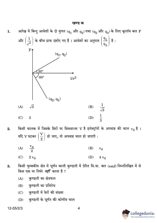
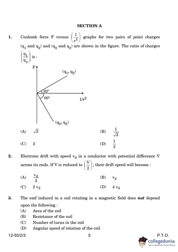
Coulomb force \( F \) versus \( \frac{1}{r^2} \) graphs for two pairs of point charges \( (q_1, q_2) \) and \( (q_2, q_3) \) are shown in the figure. The ratio of charges \( \left| \frac{q_1}{q_3} \right| \) is:

View Solution
From Coulomb's law: \[ F = k \frac{q_1 q_2}{r^2} \]
Since the force vs. \( \frac{1}{r^2} \) graph is given, the slope of the graph represents \( q_1 q_2 \) and \( q_2 q_3 \).
Let the slopes of the given graphs be: \[ m_1 = k q_1 q_2, \quad m_2 = k q_2 q_3. \]
From the diagram, the angle between the two slopes is given as 30° and 60°. Using the property of slopes:
F = (kq₁q₂)/r²
F vs 1/r²
(kq₁q₂)/(kq₂q₃) = (tan 30°)/(tan 60°)
q₁/q₃ = (1/√3)/√3
q₁/q₃ = (1/√3) * (1/√3)
q₁/q₃ = 1/3
Hence, the correct answer is: 1/3Quick Tip: In problems involving Coulomb’s law and graphs, identify slopes carefully and use trigonometric relations when angles are involved.
Electrons drift with speed \( v_d \) in a conductor with potential difference \( V \) across its ends. If \( V \) is reduced to \( \frac{V}{2} \), their drift speed will become:
View Solution
These equations describe the drift velocity (\(v_d\)) of a charged particle, such as an electron, in an electric field.
Drift velocity is the average velocity a particle attains due to an electric field, representing a net drift despite collisions.
Equation 1: \[ v_d = \frac{e E t}{m} \]
where:
\quad \(v_d\) is the drift velocity,
\quad \(e\) is the charge of the particle (e.g., elementary charge for an electron),
\quad \(E\) is the electric field strength,
\quad \(t\) is the time,
\quad \(m\) is the mass of the particle.
This equation shows that \(v_d\) is directly proportional to \(E\) and \(t\), and inversely proportional to \(m\).
Equation 2: \[ v_d = \frac{e V t}{m l} \]
where:
\quad \(v_d\) is the drift velocity,
\quad \(e\) is the charge of the particle,
\quad \(V\) is the potential difference (voltage),
\quad \(t\) is the time,
\quad \(m\) is the mass of the particle,
\quad \(l\) is the distance.
Since \(E = \frac{V}{l}\), this equation is equivalent to Equation 1.
Equation 3: \[ v_d = \frac{v_d}{2} \]
This equation is mathematically inconsistent unless \(v_d = 0\). It likely contains a typo or requires additional context. It might represent an average or another derived quantity, but as written, it implies zero drift velocity. Quick Tip: Drift velocity is directly proportional to the potential difference. Halving the potential difference will halve the drift velocity.
The emf induced in a coil rotating in a magnetic field does not depend upon the following:
View Solution
The emf induced in a coil rotating in a uniform magnetic field is given by: \[ \mathcal{E} = N B A \omega \sin(\omega t), \]
where:
\( N \) is the number of turns in the coil,
\( B \) is the magnetic field strength,
\( A \) is the area of the coil,
\( \omega \) is the angular speed of rotation.
From this equation, it is evident that emf depends on \( A \), \( N \), \( B \), and \( \omega \). However, the resistance of the coil does not appear in the expression for induced emf—it only affects the current flowing in the circuit, not the emf itself.
Thus, the correct answer is: \[ (2) Resistance of the coil. \] Quick Tip: Induced emf in a rotating coil is independent of its resistance; it is governed by Faraday’s Law and depends on area, number of turns, and angular speed.
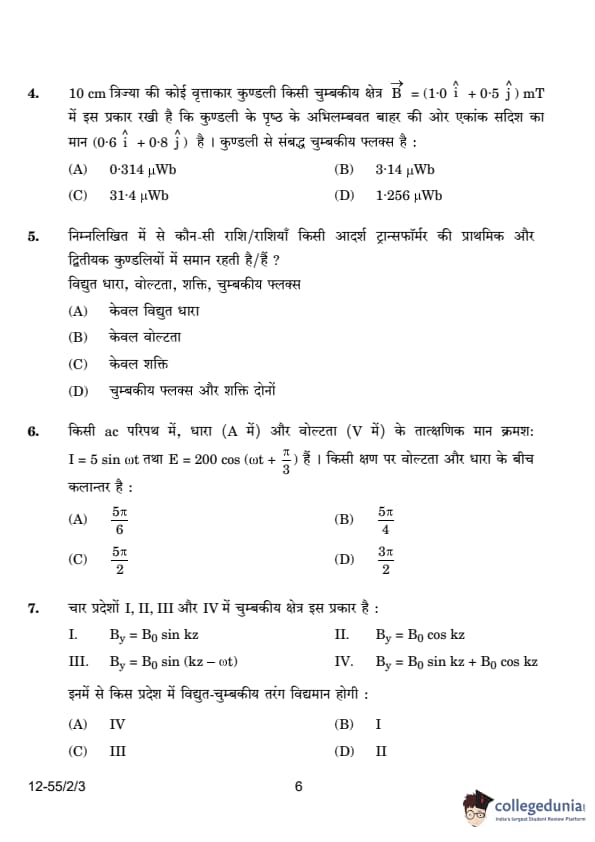
A circular coil of radius 10 cm is placed in a magnetic field \( \vec{B} = (1.0 \hat{i} + 0.5 \hat{j}) \, mT \) such that the outward unit vector normal to the surface of the coil is \( (0.6 \hat{i} + 0.8 \hat{j}) \). The magnetic flux linked with the coil is:
View Solution
The magnetic flux \( \Phi_B \) linked with the coil is given by: \[ \Phi_B = B A \cos \theta. \]
Where:
\( B \) is the magnetic field,
\( A \) is the area of the coil,
\( \theta \) is the angle between the normal to the surface of the coil and the magnetic field.
The area of the coil is: \[ A = \pi r^2 = \pi (0.1)^2 = 0.0314 \, m^2. \]
The magnetic field \( B \) is the dot product of the vector \( \vec{B} \) and the unit vector normal to the surface of the coil: \[ \vec{B} \cdot \hat{n} = (1.0 \hat{i} + 0.5 \hat{j}) \cdot (0.6 \hat{i} + 0.8 \hat{j}) = 1.0 \times 0.6 + 0.5 \times 0.8 = 0.6 + 0.4 = 1.0 \, mT. \]
Thus, the magnetic flux is: \[ \Phi_B = 1.0 \times 0.0314 = 0.0314 \, Wb = 31.4 \, \mu Wb. \] Quick Tip: For calculating magnetic flux, remember to use the dot product to find the effective magnetic field component normal to the coil's surface.
Which of the following quantity/quantities remains same in primary and secondary coils of an ideal transformer? Current, Voltage, Power, Magnetic flux
View Solution
In an ideal transformer:
The magnetic flux remains the same in both the primary and secondary coils because the transformer operates based on mutual induction, where the same magnetic flux links both coils.
The power is conserved in an ideal transformer, meaning the input power (in the primary coil) is equal to the output power (in the secondary coil), ignoring losses.
Thus, the quantities that remain the same are: \[ \boxed{Magnetic flux and Power both}. \] Quick Tip: In an ideal transformer, the power is conserved, and the magnetic flux linking the primary and secondary coils remains unchanged.
In an AC circuit, the instantaneous values of current (in A) and voltage (in V) are given as: \[ I = 5 \sin \omega t, \quad E = 200 \cos (\omega t + \frac{\pi}{3}) \]respectively. The phase difference between voltage and current at any instant is:
View Solution
The given current equation is:
\[ I = 5 \sin \omega t \]
which implies that the phase of current is \( \theta_I = 0 \).
The given voltage equation is:
\[ E = 200 \cos (\omega t + \frac{\pi}{3}) \]
We convert \( \cos \) into a sine function:
\[ \cos(\theta) = \sin(\theta + \frac{\pi}{2}) \]
Thus,
\[ E = 200 \sin (\omega t + \frac{\pi}{3} + \frac{\pi}{2}) \]
\[ E = 200 \sin (\omega t + \frac{5\pi}{6}) \]
This shows that the phase of voltage \( \theta_V \) is \( \frac{5\pi}{6} \).
The phase difference between voltage and current is:
\[ \Delta \theta = \frac{5\pi}{6} - 0 = \frac{5\pi}{6} \]
Thus, the correct answer is \( \frac{5\pi}{6} \). Quick Tip: To determine phase difference, express all trigonometric terms in the same function (either sine or cosine).
In four regions I, II, III, and IV, the magnetic field is given by:
(a) \( \quad B_y = B_0 \sin kz\)
(b) \( \quad B_y = B_0 \cos kz\)
(c) \(\quad B_y = B_0 \sin (kz - \omega t)\)
(d) \(\quad B_y = B_0 \sin kz + B_0 \cos kz\)
The electromagnetic wave will exist in the region:
View Solution
Electromagnetic waves require both time-dependent and spatially-dependent variations in the electric and magnetic fields.
Regions I and II have only spatial dependency, meaning they represent standing waves or static field distributions, not propagating electromagnetic waves.
Region IV is just a sum of sinusoidal terms without a time-dependent phase shift.
Region III contains a time-dependent term \( (kz - \omega t) \), which signifies a propagating wave.
Thus, the correct answer is Region III. Quick Tip: For electromagnetic wave propagation, the field must be a function of both space and time in the form \( kx - \omega t \).
The momentum (in SI units) associated with a photon of energy \( 1.5 \) eV is:
View Solution
The momentum of a photon is given by: \[ p = \frac{E}{c} \]
where:
\( E = 1.5 \) eV \( = 1.5 \times 1.6 \times 10^{-19} \) J,
\( c = 3.0 \times 10^8 \) m/s.
Substituting the values: \[ p = \frac{1.5 \times 1.6 \times 10^{-19}}{3.0 \times 10^8} \]
\[ p = \frac{2.4 \times 10^{-19}}{3.0 \times 10^8} = 8 \times 10^{-28} kg·m/s. \]
Thus, the correct answer is \( 8 \times 10^{-28} \) kg·m/s. Quick Tip: Photon momentum is calculated using \( p = \frac{E}{c} \), where \( E \) is energy in joules and \( c \) is the speed of light.
An n-type semiconducting Si is obtained by doping intrinsic Si with:
View Solution
n-type semiconductors are formed by adding pentavalent (donor) impurities to intrinsic silicon.
Phosphorus (P) is a pentavalent element, meaning it has five valence electrons.
When doped into silicon, it donates extra electrons, increasing the number of free electrons in the conduction band, making the material n-type.
On the other hand:
Aluminum (Al), Boron (B), and Indium (In) are trivalent elements, which create p-type semiconductors by generating holes.
Thus, the correct answer is Phosphorus (P). Quick Tip: n-type semiconductors are doped with pentavalent elements (e.g., P, As, Sb), while p-type semiconductors are doped with trivalent elements (e.g., B, Al, In).
Energy levels A, B, and C of an atom correspond to increasing values of energy i.e., \( E_A < E_B < E_C \). Let \( \lambda_1 \), \( \lambda_2 \), and \( \lambda_3 \) be the wavelengths of radiation corresponding to the transitions C to B, B to A, and C to A, respectively. The correct relation between \( \lambda_1 \), \( \lambda_2 \), and \( \lambda_3 \) is:
View Solution
The wavelengths of radiation corresponding to atomic transitions are related by the energy difference between the levels. According to the Rydberg formula for transitions: \[ \frac{1}{\lambda} = R \left( \frac{1}{n_1^2} - \frac{1}{n_2^2} \right), \]
where \( R \) is the Rydberg constant and \( n_1 \) and \( n_2 \) are the principal quantum numbers of the initial and final states, respectively. For the transitions described, the relation between the wavelengths is: \[ \frac{1}{\lambda_1} + \frac{1}{\lambda_2} = \frac{1}{\lambda_3}. \] Quick Tip: For transitions between energy levels, use the Rydberg formula to relate wavelengths to energy differences.
When a p-n junction diode is subjected to reverse biasing:
View Solution
In reverse biasing, the external voltage opposes the potential barrier of the p-n junction, which causes the depletion region to widen. This happens because the external voltage increases the barrier height, preventing current from flowing (except for a very small leakage current). Quick Tip: In reverse bias, the barrier height increases and the depletion region widens, leading to the prevention of current flow.
An alpha particle approaches a gold nucleus in Geiger-Marsden experiment with kinetic energy \( K \). It momentarily stops at a distance \( d \) from the nucleus and reverses its direction. Then \( d \) is proportional to:
View Solution
To determine the relationship between the distance \( d \) at which the alpha particle stops and its initial kinetic energy \( K \), we can use the principles of energy conservation and the Coulomb force.
1. Initial Kinetic Energy: The alpha particle has an initial kinetic energy \( K \).
2. Potential Energy at Distance \( d \): When the alpha particle stops, all its kinetic energy is converted into electrostatic potential energy. The potential energy \( U \) between the alpha particle (charge \( +2e \)) and the gold nucleus (charge \( +79e \)) at a distance \( d \) is given by:
\[ U = \frac{1}{4\pi\epsilon_0} \cdot \frac{(2e)(79e)}{d} \]
where \( \epsilon_0 \) is the permittivity of free space.
3. Energy Conservation: At the point where the alpha particle stops, its kinetic energy is zero, and its potential energy equals the initial kinetic energy:
\[ K = \frac{1}{4\pi\epsilon_0} \cdot \frac{158e^2}{d} \]
4. Solving for \( d \): Rearrange the equation to solve for \( d \):
\[ d = \frac{1}{4\pi\epsilon_0} \cdot \frac{158e^2}{K} \]
This shows that \( d \) is inversely proportional to \( K \):
\[ d \propto \frac{1}{K} \]
Therefore, the correct answer is:
\[ \boxed{C} \] Quick Tip: The distance at which a charged particle stops due to Coulomb's interaction is inversely proportional to the square root of its kinetic energy.
Assertion (A): An electron and a proton enter with the same momentum \( \vec{p} \) in a magnetic field \( \vec{B} \) such that \( \vec{p} \perp \vec{B} \). Then both describe a circular path of the same radius.
Reason (R): The radius of the circular path described by the charged particle (charge \( q \), mass \( m \)) moving in the magnetic field \( \vec{B} \) is given by \( r = \frac{mv}{qB} \).
View Solution
The assertion is correct because when an electron and a proton enter the magnetic field with the same momentum, they experience the same force due to their charge and follow a circular path with the same radius. The radius of the circular path is given by the formula:
\[ r = \frac{p}{qB} \]
Since both have the same momentum and the formula depends on \( p \), the radii of their circular paths will be the same. Thus, both the assertion and the reason are true, and the reason correctly explains the assertion. Quick Tip: For a charged particle in a magnetic field, the radius of the circular motion depends on its momentum, charge, and magnetic field strength.
Assertion (A): The magnifying power of a compound microscope is negative.
Reason (R): The final image formed is erect with respect to the object.
View Solution
The assertion is correct because the magnifying power of a compound microscope is considered negative, as the final image is inverted relative to the object. However, the reason is incorrect because the final image formed is not erect but rather inverted with respect to the object. Therefore, the assertion is true, but the reason is false. Quick Tip: A compound microscope produces an inverted image, and its magnifying power is conventionally taken as negative.
Assertion (A): Lenz's law is a consequence of the law of conservation of energy.
Reason (R): There is no power loss in an ideal inductor.
View Solution
Lenz’s law is a consequence of the conservation of energy, as it ensures that the induced current always flows in a direction that opposes the change in magnetic flux. The statement that there is no power loss in an ideal inductor is also true because an ideal inductor does not dissipate energy; instead, it stores energy in the magnetic field. However, this does not directly explain Lenz’s law, making option (2) the correct choice. Quick Tip: Lenz’s law follows the principle of conservation of energy, while an ideal inductor stores energy without dissipation, making both statements true but unrelated in explanation.
Assertion (A): Photoelectric current increases with an increase in intensity of incident radiation, for a given frequency of incident radiation and the accelerating potential.
Reason (R): Increase in the intensity of incident radiation results in an increase in the number of photoelectrons emitted per second and hence an increase in the photocurrent.
View Solution
When the intensity of incident radiation increases (for a constant frequency), the number of photons hitting the surface increases. This results in the emission of more photoelectrons per second, thereby increasing the photocurrent. This explanation aligns perfectly with the assertion. Quick Tip: The intensity of radiation affects the number of photoelectrons emitted, which in turn increases the photocurrent.
An electric field \( E \) is maintained in a wire of length \( l \) and cross-sectional area \( a \). Derive the relation between the current density \( \sigma \) in the wire and the electric field \( E \).
View Solution
From Ohm’s Law: \[ V = IR \]
The resistance \( R \) of the wire is given by: \[ R = \frac{\rho l}{A} \]
where \( \rho \) is the resistivity of the material.
Substituting in Ohm's Law: \[ E l = I \frac{\rho l}{A} \]
Rearranging: \[ E = \frac{I}{A} \rho \]
Since current density is given by: \[ J = \frac{I}{A} \]
We obtain the final relation: \[ E = J \rho \]
Since conductivity \( \sigma \) is the reciprocal of resistivity (\( \sigma = \frac{1}{\rho} \)), we can write: \[ J = \sigma E \]
Thus, the required relation between current density and electric field is: \[ J = \sigma E. \] Quick Tip: Current density is directly proportional to the electric field in a conductor, with conductivity as the proportionality constant.
How does the energy gap of an intrinsic semiconductor effectively change when doped with (a) a trivalent impurity, and (b) a pentavalent impurity? Justify your answer in each case.
View Solution
(i) Trivalent Impurity (p-type Semiconductor):
A trivalent impurity (e.g., Boron) introduces an acceptor energy level just above the valence band.
This reduces the effective energy gap since electrons can be excited with less energy.
\[ E_A \approx 0.01 - 0.05 eV above E_V \]
Conclusion: The energy gap effectively decreases.
(ii) Pentavalent Impurity (n-type Semiconductor):
A pentavalent impurity (e.g., Phosphorus) introduces a donor energy level just below the conduction band.
This facilitates electron excitation, reducing the effective energy gap.
\[ E_D \approx 0.01 eV below E_C \]
Conclusion: The energy gap effectively decreases.
Quick Tip: Doping intrinsic semiconductors with acceptor (trivalent) or donor (pentavalent) impurities introduces new energy levels near the valence or conduction band, effectively reducing the energy gap.
Two waves, each of amplitude \( a \) and frequency \( \omega \) emanating from two coherent sources of light superpose at a point. If the phase difference between the two waves is \( \phi \), obtain an expression for the resultant intensity at that point.
View Solution
Let the equations of the two waves be: \[ x_1 = a \cos(\omega t), \] \[ x_2 = a \cos(\omega t + \phi), \]
where \( a \) is the amplitude, \( \omega \) is the frequency, and \( \phi \) is the phase difference.
The resultant displacement \( x \) is: \[ x = x_1 + x_2 = a \cos(\omega t) + a \cos(\omega t + \phi) = a ( \cos(\omega t) + \cos(\omega t + \phi) ). \]
Using the trigonometric identity: \[ \cos A + \cos B = 2 \cos\left(\frac{A+B}{2}\right) \cos\left(\frac{A-B}{2}\right), \]
we get: \[ x = 2a \cos\left(\frac{\phi}{2}\right) \cos\left(\omega t + \frac{\phi}{2}\right). \]
The intensity \( I \) is proportional to the square of the amplitude: \[ I = K (Amplitude)^2 = K \left(2a \cos\left(\frac{\phi}{2}\right)\right)^2 = 4K a^2 \cos^2\left(\frac{\phi}{2}\right). \]
Let \( I_0 = Ka^2 \) be the intensity of each incident wave. Thus, the resultant intensity is: \[ I = 4I_0 \cos^2\left(\frac{\phi}{2}\right). \] Quick Tip: The intensity of two superimposed waves depends on the square of the cosine of half the phase difference.
What is the effect on the interference pattern in Young's double-slit experiment when (i) the source slit is moved closer to the plane of the slits, and (ii) the separation between the two slits is increased? Justify your answers.
View Solution
(i) As the source slit is moved closer to the plane of the slits, the sharpness of the interference pattern decreases. This happens because the light from different parts of the source overlaps and the fringes begin to blur, eventually disappearing if the slit is moved too close. The fringe sharpness is affected by the ratio \( \frac{s}{d} \), where \( s \) is the distance between the source and the slits, and \( d \) is the separation between the slits. If \( s \) decreases, the sharpness of the interference pattern decreases.
(ii) As the separation between the two slits increases, the fringe spacing \( \beta \) decreases. The fringe spacing is given by: \[ \beta = \frac{\lambda D}{d}, \]
where \( \lambda \) is the wavelength of light, \( D \) is the distance from the slits to the screen, and \( d \) is the slit separation. As \( d \) increases, \( \beta \) decreases, and the fringes become closer together. Quick Tip: The sharpness of interference fringes depends on the relative distances between the source, slits, and screen. Adjusting these distances changes the fringe spacing.
In the Bohr model of the hydrogen atom, find the ratio of the period of revolution of the electron in the orbit \( n = 2 \) to that in the orbit \( n = 1 \).
View Solution
The period of revolution \( T \) of an electron in the Bohr orbit is given by: \[ T = \frac{2 \pi r_n}{v_n} \]
From Bohr’s model, the radius of the \( n \)th orbit is: \[ r_n \propto n^2 \]
and the velocity of the electron is: \[ v_n \propto \frac{1}{n} \]
Thus, the period of revolution: \[ T \propto \frac{n^2}{\frac{1}{n}} = n^3 \]
Therefore, the ratio of periods for \( n_2 = 2 \) and \( n_1 = 1 \) is: \[ \frac{T_2}{T_1} = \left( \frac{n_2}{n_1} \right)^3 = \left( \frac{2}{1} \right)^3 = 8. \]
Final Answer: \[ \frac{T_2}{T_1} = 8. \] Quick Tip: The period of revolution of an electron in a Bohr orbit is proportional to the cube of the principal quantum number: \( T \propto n^3 \).
A convex lens (\( n = 1.52 \)) has a focal length of 15.0 cm in air. Find its focal length when it is immersed in a liquid of refractive index 1.65. What will be the nature of the lens?
View Solution
Lens Maker's Formula
Let fa be the focal length of the convex lens in air and fl be the focal length of the convex lens in liquid.
Let ng be the refractive index of the lens material, na be the refractive index of air, and nl be the refractive index of the liquid.
Let R1 and R2 be the radii of curvature of the lens surfaces.
The lens maker's formula for a lens in air is given by:
1 / fa = (ng / na - 1) * (1 / R1 - 1 / R2)
The lens maker's formula for a lens in liquid is given by:
1 / fl = (ng / nl - 1) * (1 / R1 - 1 / R2)
We are given that ng = 1.52, na = 1, and nl = 1.65.
Dividing the second equation by the first equation, we get:
fl / fa = ( (ng / na) - 1 ) / ( (ng / nl) - 1 )
Substitute the values:
fl / fa = ( (1.52 / 1) - 1 ) / ( (1.52 / 1.65) - 1 )
We calculate this step by step:
        fl / fa = (1.52 - 1) / ((1.52 - 1.65) / 1.65)
        fl / fa = 0.52 / (-0.13 / 1.65)
        fl / fa = (0.52 * 1.65) / -0.13
        fl / fa = 0.858 / -0.13
        fl / fa = -6.6
Thus, fl = -6.6 fa.
Given that fa = 15 cm, we have:
fl = -6.6 * 15 = -99 cm
Since fl is negative, the convex lens in the liquid behaves as a diverging lens, or a concave lens.
Final Answer:
The final answer is -99 cm
Two long, straight, parallel conductors carry steady currents in opposite directions. Explain the nature of the force of interaction between them. Obtain an expression for the magnitude of the force between the two conductors. Hence define one ampere.
View Solution
The force between two parallel conductors carrying currents is due to the magnetic field produced by one conductor acting on the other. The force is repulsive if the currents are in opposite directions and attractive if the currents are in the same direction.
The magnitude of the force per unit length between two conductors is given by Ampère's force law: \[ F = \frac{\mu_0 I_1 I_2}{2 \pi d}, \]
where:
\( I_1 \) and \( I_2 \) are the currents in the two conductors,
\( d \) is the distance between them,
\( \mu_0 \) is the permeability of free space.
One ampere is defined as the current that, when flowing through two parallel conductors one meter apart, produces a force of \( 2 \times 10^{-7} \, N/m \) on each conductor. Quick Tip: The force between two conductors depends on the current in each conductor and the distance between them.
Obtain an expression for the torque \( \tau \) acting on a current-carrying loop in a uniform magnetic field \( \vec{B} \). Draw the necessary diagram.
View Solution
The torque on a current loop in a magnetic field is given by the expression: \[ \tau = I A B \sin \theta, \]
where:
\( I \) is the current in the loop,
\( A \) is the area of the loop,
\( B \) is the magnetic field strength,
\( \theta \) is the angle between the normal to the loop and the magnetic field.
\

The forces on arms BC and DA are equal and opposite and cancel each other out, while the forces on arms AB and CD form a couple, leading to a torque.
\[ \tau = I A B \sin \theta. \] Quick Tip: The torque on a current loop in a magnetic field depends on the current, area of the loop, and the angle between the magnetic field and the loop's normal.
(a) On what factors does the speed of an electromagnetic wave in a medium depend?
(b) How is an electromagnetic wave produced?
(c) Sketch a schematic diagram depicting the electric and magnetic fields for an electromagnetic wave propagating along the z-axis.
View Solution
(a) The speed \( v \) of an electromagnetic wave in a medium depends on:
The permittivity \( \epsilon \) of the medium.
The magnetic permeability \( \mu \) of the medium.
The speed of EM waves is given by: \[ v = \frac{1}{\sqrt{\mu \epsilon}}. \]
(b) Electromagnetic waves are produced by oscillating or accelerated charges, such as electrons in an antenna. These oscillating charges generate both electric and magnetic fields that propagate through space as an electromagnetic wave.
(c) The electric and magnetic fields for an electromagnetic wave propagating along the z-axis are perpendicular to each other and the direction of propagation. The electric field oscillates along the x-axis and the magnetic field along the y-axis, as shown in the diagram:

Quick Tip: The speed of electromagnetic waves in a medium depends on the permittivity and permeability of the medium.
An AC voltage \( v_i = 140 \sin (100 \pi t) \) V is applied to the primary coil having 200 turns of an ideal transformer, and it supplies a power of 5 kW. If the secondary coil has 1000 turns, find:
(a) the output voltage,
(b) the instantaneous voltage across the secondary coil, and
(c) the current in the secondary coil. (Take \( \sqrt{2} = 1.4 \))
View Solution
(a) Finding Output Voltage
The RMS voltage of the primary coil is: \[ V_p (rms) = \frac{140}{\sqrt{2}} = \frac{140}{1.4} = 100V \]
Using the transformer voltage ratio: \[ V_s = \frac{N_s}{N_p} V_p \]
Substituting the values: \[ V_s = \frac{1000}{200} \times 100 = 500V. \]
(b) Finding Instantaneous Voltage
The instantaneous voltage across the secondary coil is given by: \[ v_s = V_s \sqrt{2} \sin (100 \pi t) \]
Substituting \( V_s = 500V \): \[ v_s = 500 \times 1.4 \sin (100 \pi t) = 700 \sin (100 \pi t). \]
(c) Finding Current in the Secondary Coil
Since it is an ideal transformer: \[ Power Output = Power Input \] \[ P_s = V_s I_s \]
Rearranging for \( I_s \): \[ I_s = \frac{P_s}{V_s} = \frac{5000}{500} = 10A. \]
Final Answers:
(a) \( V_s = 500V \)
(b) \( v_s = 700 \sin (100 \pi t) \)
(c) \( I_s = 10A \)
Quick Tip: For ideal transformers, use the voltage and current transformation ratios: \[ V_s = \frac{N_s}{N_p} V_p, \quad I_s = \frac{N_p}{N_s} I_p. \]
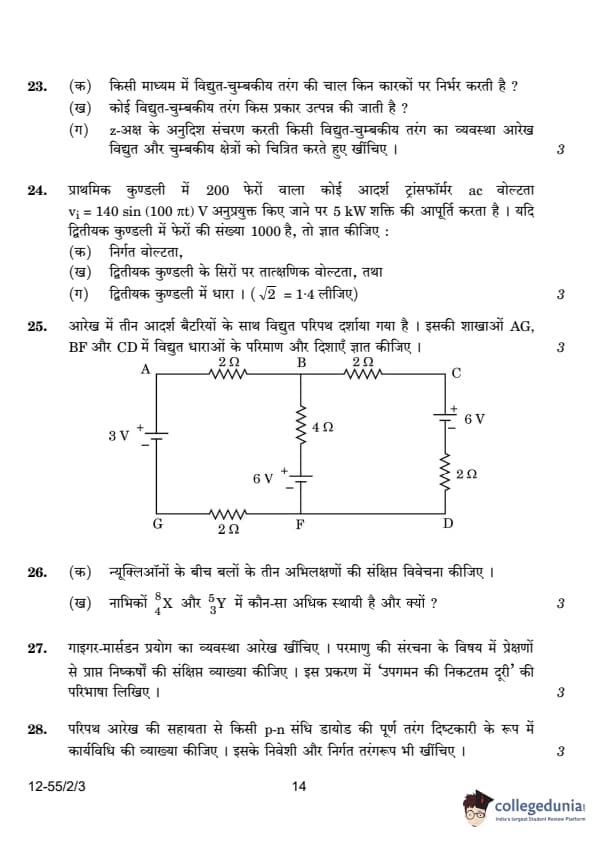
The figure shows a circuit with three ideal batteries. Find the magnitude and direction of currents in the branches AG, BF and CD.

View Solution
By applying Kirchhoff’s laws to the circuit, we can determine the currents in the different branches.
First, we use Kirchhoff’s current law at point B: \[ I_1 + I_2 = I_3 \]
Next, applying Kirchhoff’s loop rule for the closed loop AGFBA: \[ 3 + 2I_3 - 6 + 4I_2 + 2I_3 = 0 \]
Simplifying: \[ I_2 + I_3 = \frac{3}{4} \]
We substitute this in another equation based on another loop, BFDCB: \[ -4I_2 + 6 + 2I_1 - 6 + 2I_1 = 0 \]
Which simplifies to: \[ I_2 = I_1 \]
By solving the equations, we find: \[ I_1 = \frac{1}{4} \, A, \, I_2 = \frac{1}{4} \, A, \, I_3 = \frac{1}{2} \, A. \] Quick Tip: Kirchhoff’s laws are helpful for analyzing circuits with multiple batteries and resistors to determine currents and voltages.
Briefly discuss three characteristics of the forces between nucleons.
View Solution
The nuclear force is the force that binds protons and neutrons in an atomic nucleus. Its key characteristics are:
1. Saturation Property: Nuclear forces are strong but act only between a limited number of neighboring nucleons, meaning they do not increase indefinitely with additional nucleons.
2. Short-Range Nature: These forces are attractive for distances larger than a certain range (\( r_0 \)), but become strongly repulsive at very short distances to prevent collapse.
3. Charge Independence: The nuclear force is the same between neutron-neutron (n-n), neutron-proton (n-p), and proton-proton (p-p) interactions, meaning it does not depend on electric charge.
4. Stronger than Gravitational Force: Nuclear forces are much stronger than gravitational forces but act over a much shorter range.
(Any three of the above can be considered as correct answers.) Quick Tip: Nuclear forces are short-ranged, extremely strong, and independent of electric charge, making them distinct from electromagnetic and gravitational forces.
Which out of \( ^{8}_{4}X \) and \( ^{5}_{3}Y \) nuclei is more stable and why?
View Solution
To determine the stability of a nucleus, the neutron-to-proton (N/P) ratio is a crucial factor.
For \( ^{8}_{4}X \):
Number of neutrons \( = 8 - 4 = 4 \).
Number of protons \( = 4 \).
Neutron-to-proton ratio \( = \frac{4}{4} = 1.0 \).
For \( ^{5}_{3}Y \):
Number of neutrons \( = 5 - 3 = 2 \).
Number of protons \( = 3 \).
Neutron-to-proton ratio \( = \frac{2}{3} \approx 0.67 \).
Since a higher neutron-to-proton ratio generally leads to greater nuclear stability, \( ^{8}_{4}X \) is more stable compared to \( ^{5}_{3}Y \).
Final Answer: \( ^{8}_{4}X \) is more stable because it has a more favorable neutron-to-proton ratio. Quick Tip: A nucleus is more stable when its neutron-to-proton ratio is closer to the ideal value for its size. Generally, light elements prefer a 1:1 ratio.
Draw a schematic arrangement of the Geiger-Marsden experiment. Briefly explain the conclusions drawn from the observations about the structure of an atom. Define ‘distance of closest approach’ in this case.
View Solution
(a) Schematic Diagram of Geiger-Marsden Experiment

(b) Conclusions from the Experiment
1. Most of the atom is empty space: Since most alpha particles passed through the gold foil undeflected, it indicates that atoms consist mostly of empty space.
2. Presence of a small, dense, positively charged nucleus: Some alpha particles were deflected at large angles, suggesting the existence of a small, massive, positively charged core (nucleus).
3. Electrons orbit around the nucleus: Similar to planets orbiting the sun, electrons revolve around the nucleus.
4. Size of the nucleus: The nucleus is estimated to be about \( 10^{-15} \) m to \( 10^{-14} \) m in size, much smaller than the atom itself.
### (c) Definition of Distance of Closest Approach
The distance of closest approach \( r_c \) is the minimum distance an alpha particle can get to the nucleus before being repelled back due to electrostatic repulsion. It is given by:
\[ r_c = \frac{1}{4\pi\varepsilon_0} \cdot \frac{2Ze^2}{K} \]
where:
\( Z \) is the atomic number of the nucleus,
\( e \) is the charge of an electron,
\( K \) is the initial kinetic energy of the alpha particle.
Quick Tip: The Geiger-Marsden experiment led to the Rutherford model of the atom, which introduced the concept of a small nucleus at the center of the atom.
With the help of a circuit diagram, explain the working of a p-n junction diode as a full-wave rectifier. Draw its input and output waveforms.
View Solution

(b) Working of Full Wave Rectifier
A full-wave rectifier converts AC input voltage into DC output voltage using two diodes and a center-tapped transformer. The process works in two half cycles:
1. Positive Half Cycle:
When the AC input voltage is positive, the terminal A is positive and B is negative.
Diode \( D_1 \) is forward-biased and conducts current.
Diode \( D_2 \) is reverse-biased and does not conduct.
The current flows through load \( R_L \) in a specific direction, creating a positive output voltage.
2. Negative Half Cycle:
When the AC input voltage is negative, the terminal A is negative and B is positive.
Diode \( D_1 \) is reverse-biased and does not conduct.
Diode \( D_2 \) is forward-biased and conducts current.
Again, the current flows through load \( R_L \) in the same direction, ensuring a continuous positive voltage at the output.
Thus, the full-wave rectifier converts both half cycles of AC into pulsating DC.
(c) Input and Output Waveforms
Input waveform (AC): A sinusoidal wave that oscillates between positive and negative values.
Output waveform (DC): A pulsating waveform where both half cycles are positive.
Final Output
The average DC output voltage is higher than a half-wave rectifier.
To obtain a smooth DC voltage, a capacitor filter is used after the rectifier.
Quick Tip: A full-wave rectifier converts both half cycles of AC into pulsating DC, making it more efficient than a half-wave rectifier.
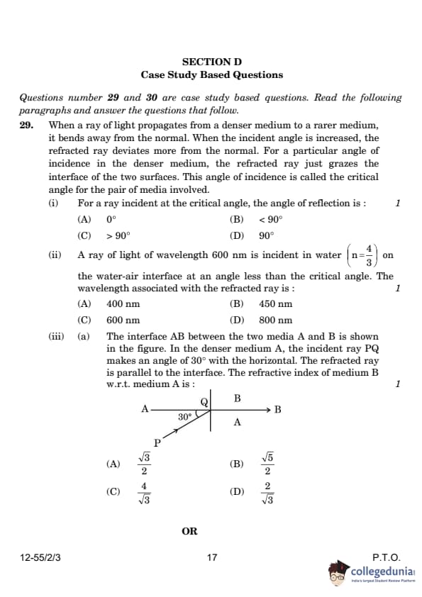
When a ray of light propagates from a denser medium to a rarer medium, it bends away from the normal. When the incident angle is increased, the refracted ray deviates more from the normal. For a particular angle of incidence in the denser medium, the refracted ray just grazes the interface of the two surfaces. This angle of incidence is called the critical angle for the pair of media involved.
(i) For a ray incident at the critical angle, the angle of reflection is:
View Solution
The angle of incidence at the critical angle is the angle at which the refracted ray grazes the interface, i.e., it refracts along the boundary. At this point, the angle of refraction is 90◦ , so by the law of reflection, the angle of reflection must also be 90◦ . Thus, the correct answer is: (D) 90◦ .
A ray of light of wavelength 600 nm is incident in water (\( n = \frac{4}{3} \)) on the water-air interface at an angle less than the critical angle. The wavelength associated with the refracted ray is:
View Solution
When light passes from one medium to another, the wavelength of the light changes. The relationship between the wavelengths in the two media is given by:
\[
\lambda_2 = \lambda_1 \frac{v_2}{v_1} = \lambda_1 \frac{n_1}{n_2},
\]
where \( \lambda_1 \) is the wavelength in the first medium (water), and \( \lambda_2 \) is the wavelength in the second medium (air).
Given:
\( \lambda_1 = 600 \, \text{nm} \),
\( n_1 = \frac{4}{3} \) (water),
\( n_2 = 1 \) (air).
Thus:
\[
\lambda_2 = 600 \times \frac{4}{3} = 800 \, \text{nm}.
\]
Thus, the correct answer is:
\[
(D) 800 nm.
\]
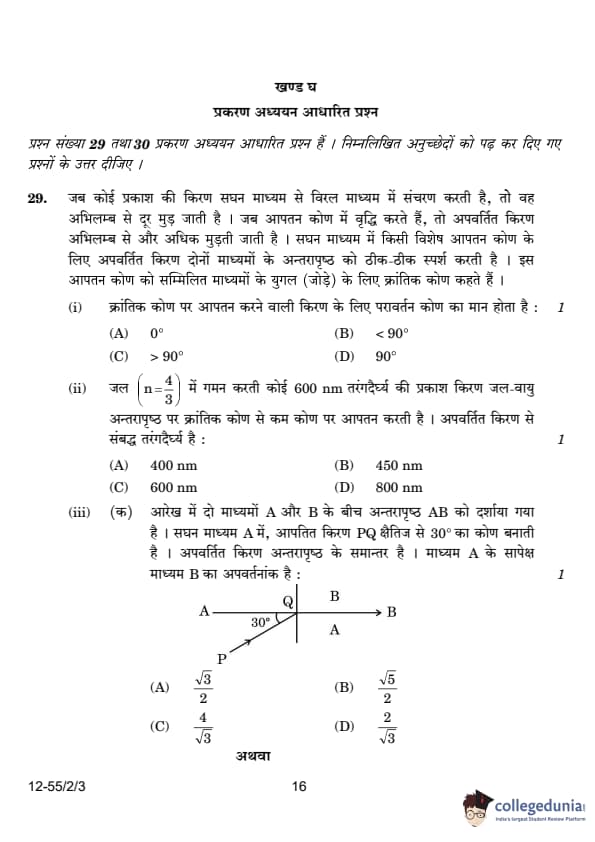
The interface AB between the two media A and B is shown in the figure. In the denser medium A, the incident ray PQ makes an angle of \( 30^\circ \) with the horizontal. The refracted ray is parallel to the interface. The refractive index of medium B with respect to medium A is:
- (1) \( \frac{\sqrt{3}}{2}\)
- (2) \( \frac{\sqrt{5}}{2}\)
- (3) \(\frac{4}{\sqrt{3}}\)
- (4) \(\frac{2}{\sqrt{3}}\)
![]()

View Solution
Refractive Index Calculation
Given:
- Medium A is denser than medium B.
- The incident ray PQ in medium A makes an angle of 30° with the horizontal.
- The refracted ray in medium B is parallel to the interface AB.
- We need to find the refractive index of medium B with respect to medium A (μBA).
Step 1: Understand the Geometry and Angles
The incident ray PQ makes an angle of 30° with the horizontal. This means the angle of incidence (i) with respect to the normal is:
i = 90° - 30° = 60°
The refracted ray is parallel to the interface AB. This means the angle of refraction (r) is 90° (since the refracted ray is parallel to the interface).
Step 2: Apply Snell's Law
Snell's Law states:
μA × sin i = μB × sin r
where:
- μA = refractive index of medium A,
- μB = refractive index of medium B,
- i = angle of incidence,
- r = angle of refraction.
From the problem:
- i = 60°,
- r = 90°.
Substitute these values into Snell's Law:
μA × sin 60° = μB × sin 90°
We know:
- sin 60° = &frac;√3;{2},
- sin 90° = 1.
So:
μA × &frac;√3;{2} = μB × 1
Step 3: Find the Refractive Index of Medium B with Respect to Medium A
The refractive index of medium B with respect to medium A is defined as:
μBA = &frac;μB;μA
From the equation in Step 2:
μB = μA × &frac;√3;{2}
Divide both sides by μA:
μBA = &frac;μB;μA = &frac;√3;{2}
Final Answer:
&boxed;&frac;√3;{2}
Thus, the correct option is (1).
Two media A and B are separated by a plane boundary. The speed of light in medium A and B is \( 2 \times 10^8 \, ms^{-1} \) and \( 2.5 \times 10^8 \, ms^{-1} \), respectively. The critical angle for a ray of light going from medium A to medium B is:
- (1) \(\sin^{-1} \frac{1}{2}\)
- (2) \(\sin^{-1} \frac{4}{5}\)
- (3) \(\sin^{-1} \frac{3}{5}\)
- (4) \(\sin^{-1} \frac{2}{5}\)
![]()

View Solution
Using Snell’s law for the critical angle \( \theta_c \): \[ n_A \sin \theta_c = n_B \sin 90^\circ = 1. \]
Hence, \[ \sin \theta_c = \frac{v_A}{v_B} = \frac{2 \times 10^8}{2.5 \times 10^8} = \frac{4}{5}. \]
Thus, the critical angle is: \[ \theta_c = \sin^{-1} \left( \frac{4}{5} \right). \]
Thus, the correct answer is: \[ \boxed{(B) \sin^{-1} \frac{4}{5}}. \]
Quick Tip: In cases involving refraction and critical angles, remember to use Snell's Law, \( n_1 \sin \theta_1 = n_2 \sin \theta_2 \), to calculate refractive indices or angles accurately.
When the terminals of a cell are connected to a conductor of resistance \( R \), an electric current flows through the circuit. The electrolyte of the cell also offers some resistance in the path of the current, like the conductor. This resistance offered by the electrolyte is called internal resistance of the cell \( r \). It depends upon the nature of the electrolyte, the area of the electrodes immersed in the electrolyte, and the temperature. Due to internal resistance, a part of the energy supplied by the cell is wasted in the form of heat.
When no current is drawn from the cell, the potential difference between the two electrodes is known as emf of the cell \( \varepsilon \). With a current drawn from the cell, the potential difference between the two electrodes is termed as terminal potential difference \( V \).
(i) Choose the incorrect statement:
(A) The potential difference \( V \) between the two terminals of a cell in a closed circuit is always less than its emf \( \varepsilon \), during discharge of the cell.
(B) The internal resistance of a cell decreases with the decrease in temperature of the electrolyte.
(C) When current is drawn from the cell then \( V = e- I r \).
(D) The graph between potential difference between the two terminals of the cell \( V \) and the current \( I \) through it is a straight line with a negative slope.
View Solution
The incorrect statement is: (B) The internal resistance of a cell decreases with the decrease in temperature of the electrolyte. The internal resistance actually increases as the temperature of the electrolyte decreases. Lower temperatures hinder the movement of ions, which increases the resistance.
Two cells of emf 2.0 V and 6.0 V and internal resistances 0.1 and 0.4 respectively, are connected in parallel. The equivalent emf of the combination will be:
View Solution
For cells connected in parallel, the equivalent emf \( \varepsilon_{eq} \) is given by the formula: \[ \varepsilon_{eq} = \frac{r_1 \varepsilon_2 + r_2 \varepsilon_1}{r_1 + r_2}, \]
where \( \varepsilon_1 \) and \( \varepsilon_2 \) are the emf values of the two cells, and \( r_1 \) and \( r_2 \) are their respective internal resistances.
Substituting the given values: \[ \varepsilon_{eq} = \frac{0.1 \times 6.0 + 0.4 \times 2.0}{0.1 + 0.4} = \frac{0.6 + 0.8}{0.5} = 2.8 \, V. \]
Thus, the correct answer is: \[ \boxed{(B)} \quad 2.8 \, V. \] Quick Tip: When cells are connected in parallel, the equivalent emf depends on the internal resistances and emfs of the cells.
Dipped in the solution, the electrode exchanges charges with the electrolyte. The positive electrode develops a potential \( V_+ \) (\( V_+ > 0 \)), and the negative electrode develops a potential \(-V_-\) (\( V_- \geq 0 \)), relative to the electrolyte adjacent to it. When no current is drawn from the cell, then:
View Solution
The electromotive force (emf) of the cell is given by the sum of the potential differences between the positive and negative electrodes relative to the electrolyte. Since both \( V_+ \) and \( V_- \) are positive, their sum is also positive, making option (A) correct.
Quick Tip: The internal resistance of a cell affects the terminal voltage when a current is drawn. For parallel-connected identical cells, the total emf remains the same, but the internal resistance is reduced.
Five identical cells, each of emf 2 V and internal resistance 0.1 \( \Omega \), are connected in parallel. This combination in turn is connected to an external resistor of 9.98 \( \Omega \). The current flowing through the resistor is:
View Solution
Since the five identical cells are connected in parallel, the total emf of the combination remains 2V. The equivalent internal resistance of the parallel combination is:
Equation 1: req = r / n = 0.1 / 5 = 0.02 Ω
Total resistance in the circuit:
Equation 2: Rtotal = Rext + req = 9.98 + 0.02 = 10 Ω
Current in the circuit:
Equation 3: I = E / Rtotal = 2 / 10 = 0.2 A
Potential difference across a cell in the open circuit is 6 V. It becomes 4 V when a current of 2 A is drawn from it. The internal resistance of the cell is:
View Solution
The internal resistance \( r \) is given by:
\[ V = E - Ir \]
Substituting the given values:
\[ 4 = 6 - (2 \times r) \]
\[ 2r = 2 \]
\[ r = 1.0 \Omega \] Quick Tip: The internal resistance of a cell affects the terminal voltage when a current is drawn. For parallel-connected identical cells, the total emf remains the same, but the internal resistance is reduced.
Give any two differences between the interference pattern obtained in Young's double-slit experiment and a diffraction pattern due to a single slit.
View Solution
The interference pattern obtained in Young's double-slit experiment has equally spaced bright bands, with constant intensity. In contrast, the diffraction pattern from a single slit shows maxima and minima, where the maxima become weaker on either side of the central maximum.
| Interference | Diffraction |
|---|---|
| 1. Bands are equally spaced. | 1. Bands are not equally spaced. |
| 2. Intensity of bright bands is the same. | 2. Intensity of maxima decreases on either side of the central maxima. |
| 3. First maxima is at an angle λ/a. | 3. First minima is at an angle λ/a. |
Draw an intensity distribution graph in case of a double-slit interference pattern.
View Solution

The graph depicts maxima and minima due to constructive and destructive interference, with maxima at integer multiples of \( \lambda \) and minima at odd multiples of \( \lambda / 2 \). Quick Tip: The intensity distribution for a double-slit interference pattern follows a sinusoidal curve, with alternating bright and dark bands representing constructive and destructive interference.
In Young's double-slit experiment using monochromatic light of wavelength \( \lambda \), the intensity of light at a point on the screen, where path difference is \( \lambda \), is \( K \) units. Find the intensity of light at a point on the screen where the path difference is \( \lambda / 6 \).
View Solution
We know that the intensity at a point in Young's double-slit experiment is given by: \[ I = I_0 \cos^2 \left( \frac{\pi \Delta}{\lambda} \right), \]
where \( I_0 \) is the maximum intensity and \( \Delta \) is the path difference.
For path difference \( \Delta = \lambda \), the intensity is \( K \). Thus, we have: \[ K = I_0 \cos^2 \left( \pi \right) = I_0. \]
Now, for the path difference \( \Delta = \lambda / 6 \), we calculate the intensity: \[ I = I_0 \cos^2 \left( \frac{\pi}{6} \right) = I_0 \times \left( \frac{\sqrt{3}}{2} \right)^2 = \frac{3}{4} I_0. \]
Since \( K = I_0 \), the intensity at a point where the path difference is \( \lambda / 6 \) is: \[ I = \frac{3}{4} K. \] Quick Tip: When the path difference is not an integer multiple of \( \lambda \), use the formula for intensity and calculate using the cosine squared function for accurate results.
Draw a labelled ray diagram of a compound microscope showing image formation at least distance of distinct vision. Derive an expression for its magnifying power.
View Solution

In a compound microscope, the objective lens forms a real, inverted, and diminished image at the focal plane of the eyepiece. The eyepiece acts as a magnifier to form a virtual, erect, and magnified image at the least distance of distinct vision.
The magnifying power \( M \) of the compound microscope is given by the product of the magnifying powers of the objective lens \( M_o \) and the eyepiece lens \( M_e \): \[ M = M_o \times M_e. \]
The magnifying power of the objective lens is given by: \[ M_o = \frac{v_o}{u_o}, \]
where \( v_o \) is the image distance and \( u_o \) is the object distance for the objective lens. Since the image is formed at the focal length of the objective lens \( f_o \), we have: \[ v_o = f_o. \]
For the eyepiece, the magnifying power is given by: \[ M_e = \frac{D}{f_e}, \]
where \( D \) is the least distance of distinct vision and \( f_e \) is the focal length of the eyepiece.
Thus, the total magnifying power is: \[ M = \frac{f_o}{u_o} \times \frac{D}{f_e}. \] Quick Tip: For a compound microscope, the magnifying power is the product of the magnifying powers of the objective and the eyepiece. The objective magnifies the object, and the eyepiece further magnifies the image formed.
A telescope consists of two lenses of focal length 100 cm and 5 cm. Find the magnifying power when the final image is formed at infinity.
View Solution
In a telescope, the magnifying power \( M \) is given by the ratio of the focal lengths of the objective and the eyepiece: \[ M = \frac{f_o}{f_e}. \]
Here, \( f_o = 100 \, cm \) and \( f_e = 5 \, cm \), so the magnifying power is: \[ M = \frac{100}{5} = 20. \]
Thus, the magnifying power of the telescope is 20. Quick Tip: The magnifying power of a telescope is simply the ratio of the focal length of the objective lens to the focal length of the eyepiece when the final image is formed at infinity.
Obtain an expression for the electric potential due to a small dipole of dipole moment \( \vec{p} \), at a point \( \vec{r} \) from its centre, for much larger distances compared to the size of the dipole.
View Solution
(a) (i) Expression for electric potential:
The electric potential due to a dipole is the sum of potentials due to the charges \( +q \) and \( -q \) separated by distance \( 2a \):
\[
V = \frac{1}{4\pi\epsilon_0} \left( \frac{q}{r_1} - \frac{q}{r_2} \right)
\]
Using the geometry of the dipole, we have:
\[
r_1^2 = r^2 + a^2 - 2a r \cos\theta, \quad r_2^2 = r^2 + a^2 + 2a r \cos\theta
\]
For \( r \gg a \), using binomial expansion and retaining first-order terms:
\[
\frac{1}{r_1} \approx \frac{1}{r} \left(1 - \frac{a \cos\theta}{r} \right), \quad \frac{1}{r_2} \approx \frac{1}{r} \left(1 + \frac{a \cos\theta}{r} \right)
\]
Substituting these into the potential equation:
\[
V = \frac{q}{4\pi\epsilon_0} \left( \frac{2a \cos\theta}{r^2} \right)
\]
Since dipole moment \( p = 2qa \), we get:
\[
V = \frac{p \cos\theta}{4\pi\epsilon_0 r^2}
\]
Three point charges \( q \), \( 2q \) and \( nq \) are placed at the vertices of an equilateral triangle. If the potential energy of the system is zero, find the value of \( n \).
View Solution
Potential energy of the system:
\[
U = \frac{k q q_2}{a} + \frac{k q_2 q_3}{a} + \frac{k q_3 q}{a}
\]
Substituting given values:
\[
U = \frac{k(q)(2q)}{a} + \frac{k(2q)(nq)}{a} + \frac{k(q)(nq)}{a} = 0
\]
\[
\frac{2q^2}{a} + \frac{2nq^2}{a} + \frac{nq^2}{a} = 0
\]
\[
2 + 2n + n = 0 \quad \Rightarrow \quad 3n = -2
\]
\[
n = -\frac{2}{3}
\]
State Gauss's law in electrostatics. Apply this to obtain the electric field E at a point near a uniformly charged infinite plane sheet:
View Solution
Gauss’s Law states:
\[
\oint \vec{E} \cdot d\vec{S} = \frac{q}{\epsilon_0}
\]
For a uniformly charged infinite sheet, the electric field is given by:
\[
E = \frac{\sigma}{2\epsilon_0}
\]
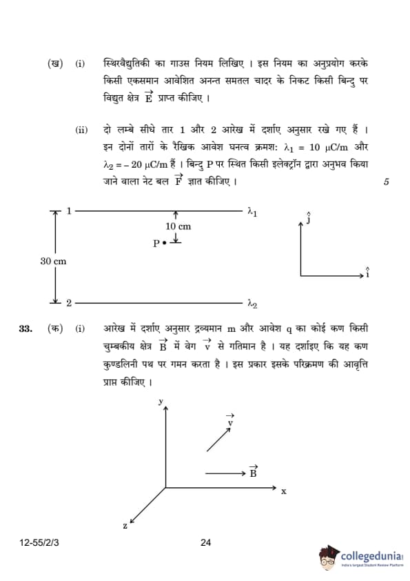
Two long straight wires 1 and 2 are kept as shown in the figure. The linear charge density of the two wires are \(\lambda\) 1 = 10 C/m and \(\lambda\)2 = -20 C/m. Find the net force F experienced by an electron held at point P:
View Solution
The electric field due to a long straight wire is given by:

\[ E = \frac{\lambda}{2\pi\epsilon_0 r} \]
For the two wires:
\[ E_1 = \frac{\lambda_1}{2\pi\epsilon_0 r_1}, \quad E_2 = \frac{\lambda_2}{2\pi\epsilon_0 r_2} \]
Substituting the given values:
\[ E_1 = \frac{10 \times 10^{-6}}{2\pi\epsilon_0 (10 \times 10^{-2})} (-\hat{j}) \]
\[ E_2 = \frac{20 \times 10^{-6}}{2\pi\epsilon_0 (20 \times 10^{-2})} (-\hat{j}) \]
Net electric field:
\[ E_{net} = \frac{10 \times 10^{-6}}{2\pi\epsilon_0} \left(\frac{1}{0.1} + \frac{2}{0.2} \right) (-\hat{j}) \]
\[ E_{net} = 3.6 \times 10^6 (-\hat{j}) N/C \]
Force on the electron:
\[ F_{net} = qE_{net} \]
\[ F_{net} = (-1.6 \times 10^{-19}) \times (3.6 \times 10^6) N \]
\[ F_{net} = 5.76 \times 10^{-13} N (\hat{j}) \] Quick Tip: The electric potential due to a dipole follows an inverse square law, whereas for a charged infinite plane, the electric field remains uniform and independent of distance.
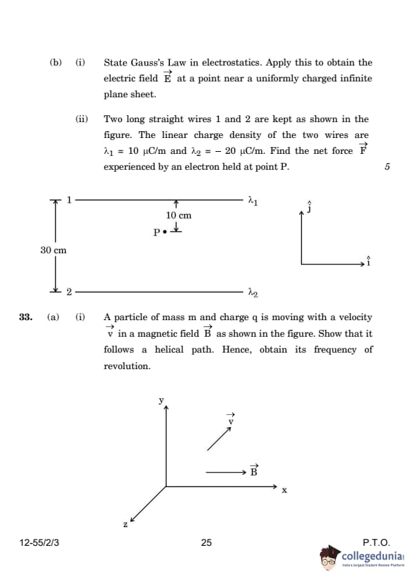
A particle of mass \( m \) and charge \( q \) is moving with a velocity \( \vec{v} \) in a magnetic field \( \vec{B} \) as shown in the figure. Show that it follows a helical path. Hence, obtain its frequency of revolution.

View Solution
The motion of a charged particle in a magnetic field can be analyzed into two components of velocity:
1. A component \( v_{\perp} \) perpendicular to the magnetic field, causing circular motion.
2. A component \( v_{\parallel} \) parallel to the magnetic field, causing linear motion along the direction of the field.
The total velocity \( v \) is the vector sum of these two components: \[ v_{\perp} = v \sin \theta, \quad v_{\parallel} = v \cos \theta. \]
The perpendicular component causes circular motion, and the parallel component causes linear motion along the magnetic field direction, resulting in a helical path.
The magnetic force provides the centripetal force for the circular motion, which gives the radius \( r \) of the circular path: \[ \frac{mv_{\perp}^2}{r} = q v_{\perp} B. \]
Solving for \( r \): \[ r = \frac{mv_{\perp}}{qB}. \]
The time period \( T \) for one complete revolution is the circumference of the circle divided by the velocity: \[ T = \frac{2\pi r}{v_{\perp}} = \frac{2\pi m}{qB}. \]
The frequency of revolution \( \nu \) is the reciprocal of the time period: \[ \nu = \frac{1}{T} = \frac{qB}{2\pi m}. \]
Thus, the particle follows a helical path with a frequency of revolution \( \nu = \frac{qB}{2\pi m} \).
Quick Tip: A charged particle moving in a magnetic field will follow a helical path due to the combination of circular motion caused by the perpendicular velocity component and linear motion caused by the parallel velocity component.
In a hydrogen atom, the electron moves in an orbit of radius \( 2 \, Å \) making \( 8 \times 10^{14} \) revolutions per second. Find the magnetic moment associated with the orbital motion of the electron.
View Solution
We are given the radius \( r = 2 \, Å = 2 \times 10^{-10} \, m \) and the frequency of revolution \( \nu = 8 \times 10^{14} \, rev/s \).
The magnetic moment \( m \) of a moving charge is given by: \[ m = I \cdot A, \]
where \( I \) is the current due to the motion of the electron, and \( A \) is the area of the circular orbit traced by the electron.
The current \( I \) is related to the charge and the frequency of revolution: \[ I = q \cdot \nu. \]
Substituting the known values for charge of the electron \( q = 1.6 \times 10^{-19} \, C \) and frequency \( \nu = 8 \times 10^{14} \, rev/s \): \[ I = 1.6 \times 10^{-19} \cdot 8 \times 10^{14} = 1.28 \times 10^{-4} \, A. \]
The area \( A \) of the circular orbit is: \[ A = \pi r^2 = \pi (2 \times 10^{-10})^2 = 1.26 \times 10^{-19} \, m^2. \]
Thus, the magnetic moment is: \[ m = I \cdot A = (1.28 \times 10^{-4}) \cdot (1.26 \times 10^{-19}) = 1.61 \times 10^{-23} \, Am^2. \]
The magnetic moment associated with the orbital motion of the electron is \( 1.61 \times 10^{-23} \, Am^2 \).
Quick Tip: The magnetic moment of a particle moving in a circular path is proportional to the current generated by the motion and the area enclosed by the path.
What is current sensitivity of a galvanometer? Show how the current sensitivity of a galvanometer may be increased. Increasing the current sensitivity of a galvanometer may not necessarily increase its voltage sensitivity. Explain.
View Solution
The current sensitivity of a galvanometer is defined as the deflection produced per unit current passing through it. It is given by the formula: \[ I_s = \frac{\theta}{I} = \frac{NBA}{K}, \]
where \( \theta \) is the angular deflection, \( I \) is the current, \( N \) is the number of turns of the coil, \( B \) is the magnetic field strength, \( A \) is the area of the coil, and \( K \) is the torsional constant.
The current sensitivity can be increased by:
Increasing the number of turns in the coil.
Increasing the area of the coil in the magnetic field.
Decreasing the torsional constant \( K \) (which means making the suspension more flexible).
Increasing the current sensitivity by changing the coil's properties may also affect the resistance of the galvanometer, which in turn can alter its voltage sensitivity. As the current sensitivity increases, the voltage sensitivity may decrease because the resistance increases, which can reduce the voltage required for full-scale deflection.
The current sensitivity is directly proportional to the number of turns and the area of the coil, but increasing the current sensitivity does not necessarily lead to an increase in voltage sensitivity. Voltage sensitivity is related to the resistance of the galvanometer, and increasing the number of turns to increase current sensitivity will also increase the resistance, thereby decreasing the voltage sensitivity. Quick Tip: The current sensitivity can be increased by increasing the number of turns, the area of the coil, or decreasing the torsional constant. However, increasing the current sensitivity may not always increase voltage sensitivity.
A moving coil galvanometer has a resistance of 15 Ω and takes 20 mA to produce full-scale deflection. How can this galvanometer be converted into a voltmeter of range 0 to 100 V?
View Solution
To convert the galvanometer into a voltmeter, we need to connect a series resistance \( R_s \) with the galvanometer. The value of \( R_s \) can be calculated using the following relation: \[ V = I_G (R + R_s), \]
where \( V \) is the full-scale deflection voltage (100 V), \( I_G \) is the current for full-scale deflection (20 mA), and \( R \) is the resistance of the galvanometer (15 Ω).
Rearranging to solve for \( R_s \): \[ R_s = \frac{V}{I_G} - R = \frac{100}{20 \times 10^{-3}} - 15 = 5000 - 15 = 4985 \, \Omega. \]
Thus, the required series resistance is 4985 Ω.
By connecting a 4985 Ω resistor in series with the galvanometer, it can be converted into a voltmeter with a full-scale range of 0 to 100 V. Quick Tip: To convert a galvanometer into a voltmeter, a high resistance is connected in series. The value of the resistance is calculated to achieve the desired voltage range for full-scale deflection.


Comments