


CBSE Class 12 Physics Question Paper 2024 PDF (Set 3- 55/3/3) is available for download here. CBSE conducted the Physics exam on March 4, 2024 from 10:30 AM to 1:30 PM. The total marks for the theory paper are 70. The question paper contains 20% MCQ-based questions, 40% competency-based questions, and 40% short and long answer type questions.
Candidates can use the link below to download the CBSE Class 12 Physics Set 3 Question Paper with detailed solutions.
CBSE Class 12 Physics Question Paper 2024 (Set 3- 55/3/3) with Answer Key
| CBSE Class 12 2024 Physics Question Paper with Answer Key | Check Solution |
CBSE Class Physics Questions with Solutions
The plates \(P_1\) and \(P_2\) of a 2 \(\mu\)F capacitor are at potentials 25 V and -25 V respectively. The charge on plate \(P_1\) will be:
\flushleft
View Solution
Given Data:
Capacitance, \( C = 2 \muF = 2 \times 10^{-6} F \)
Potential of plate P1, \( V_1 = 25 V \)
Potential of plate P2, \( V_2 = -25 V \)
Step 1: Calculate the Potential Difference
The potential difference \( V \) between the plates is:
\[ V = V_1 - V_2 = 25 V - (-25 V) = 50 V \]
Step 2: Calculate the Charge on Plate P1
Using the formula \( Q = C \times V \):
\[ Q = 2 \times 10^{-6} F \times 50 V = 100 \times 10^{-6} C = 0.1 mC \]
Conclusion:
The charge on plate P1 is \boxed{0.1 \text{ mC. Quick Tip: The charge on the plates of a capacitor is directly proportional to the potential difference and capacitance. Remember to convert the units of capacitance properly when calculating the charge.
A proton is taken from point \(P_1\) to point \(P_2\), both located in an electric field. The potentials at points \(P_1\) and \(P_2\) are -5 V and +5 V respectively. Assuming that kinetic energies of the proton at points P1 and P2 are zero, the work done on the proton is:
View Solution
Step 1: Calculating the potential difference.
The potential difference \( V \) between points \(P_1\) and \(P_2\) is calculated as: \[ V = V_{\(P_2\)} - V_{\(P_1\)} = 5 \, V - (-5 \, V) = 10 \, V \]
Step 2: Calculating the work done.
The work done \( W \) on a charge \( q \) moving through a potential difference \( V \) is given by: \[ W = qV \]
For a proton, the charge \( q = 1.602 \times 10^{-19} \, Coulombs \). Thus, the work done on the proton when moving from \(P_1\) to \(P_2\) is: \[ W = 1.602 \times 10^{-19} \, C \times 10 \, V = 1.602 \times 10^{-18} \, J \]
Rounding off slightly, the work done matches the value given in option (B). Quick Tip: Remember, the work done in moving a charge in an electric field is dependent on the potential difference and the charge itself. The direction of the electric field and the initial and final potentials will determine whether the work is done by the field or against it.
A \(2.0 \, cm\) segment of wire, carrying \(5.0 \, A\) current in the positive y-direction, lies along the y-axis as shown in the figure. Calculate the magnetic field at the point \((3 \, m, 4 \, m, 0)\) due to this wire segment:

View Solution
Step 1: Application of the Biot-Savart Law.
The magnetic field due to a segment of current-carrying wire is determined by the Biot-Savart Law, which states: \[ dB = \frac{\mu_0}{4\pi} \frac{I \, dl \times \hat{r}}{r^2} \]
where:
- \( \mu_0 = 4\pi \times 10^{-7} \, N/A^2 \) is the magnetic constant.
- \( I = 5.0 \, A \) is the current.
- \( dl = 0.02 \, m \, \hat{j} \) is the length vector of the wire segment.
- \( \hat{r} \) is the unit vector from the segment to the observation point.
Step 2: Calculation of \( r \) and \( \hat{r} \).
From the wire segment to the point (3 m, 4 m, 0): \[ r = \sqrt{3^2 + 4^2} = 5 \, m \] \[ \hat{r} = \left(\frac{3}{5}, \frac{4}{5}, 0\right) \]
Step 3: Calculation of \( dl \times \hat{r} \) and \( dB \).
Using the right-hand rule for the cross product: \[ dl \times \hat{r} = 0.02 \, \hat{j} \times \left(\frac{3}{5}, \frac{4}{5}, 0\right) = 0.02 \left( 0, 0, -\frac{3}{5} \right) = \left( 0, 0, -0.012 \right) \, \hat{k} \]
Thus, \( dB \) points in the negative \( \hat{k} \) direction. The magnitude of \( dB \) is: \[ dB = \frac{4\pi \times 10^{-7}}{4\pi} \cdot \frac{5 \cdot 0.012}{25} = \frac{10^{-7} \cdot 0.06}{25} = 2.4 \times 10^{-9} \, T = 0.24 \, nT \]
Considering the direction, the field is \( -0.24 \, nT \, \hat{k} \), matching option (C). Quick Tip: When dealing with the magnetic field calculation, always consider the right-hand rule for determining the direction of the magnetic field vector resulting from a current-carrying wire.
Which of the following is a diamagnetic substance?
View Solution
Diamagnetic substances are those that are repelled by a magnetic field. They have no unpaired electrons and their magnetic moments cancel out, resulting in a negative magnetic susceptibility.
Gadolinium (A): Gadolinium is a ferromagnetic material, not diamagnetic.
Sodium (B): Sodium is paramagnetic, not diamagnetic.
Copper chloride (C): Copper chloride is also paramagnetic due to the presence of unpaired electrons in copper.
Sodium chloride (D): Sodium chloride is a diamagnetic substance as it has no unpaired electrons, and its electrons are paired, leading to a negative magnetic susceptibility.
Thus, the correct answer is Sodium chloride. Quick Tip: Diamagnetic substances have all their electrons paired and are repelled by a magnetic field, while paramagnetic substances have unpaired electrons and are attracted to a magnetic field.
A current carrying circular loop of magnetic moment \( \vec{M} \) is suspended in a vertical plane in an external magnetic field \( \vec{B} \) such that its plane is normal to \( \vec{B} \). The work done in rotating this loop by 45° about an axis perpendicular to \( \vec{B} \) is closest to:
View Solution
Step 1: Understanding the magnetic potential energy.
The potential energy \( U \) of a magnetic dipole in a magnetic field is given by \( U = -\vec{M} \cdot \vec{B} \). Initially, the plane of the loop is normal to \( \vec{B} \), meaning \( \vec{M} \) is aligned with \( \vec{B} \), so the initial potential energy is \( U_i = -M B \).
Step 2: Calculating the final potential energy.
When the loop is rotated by 45 degrees, the angle \( \theta \) between \( \vec{M} \) and \( \vec{B} \) changes to \( 45^\circ \). The cosine of 45 degrees is \( \cos(45^\circ) = \frac{\sqrt{2}}{2} \). Thus, the final potential energy \( U_f \) becomes: \[ U_f = -MB \cos(45^\circ) = -MB \frac{\sqrt{2}}{2} \]
Step 3: Calculating the work done.
The work done \( W \) in rotating the dipole is the change in potential energy: \[ W = U_f - U_i = \left(-MB \frac{\sqrt{2}}{2}\right) - (-MB) \] \[ W = MB \left(1 - \frac{\sqrt{2}}{2}\right) \]
Given \( \sqrt{2} \approx 1.414 \), this simplifies to: \[ W = MB \left(1 - 0.707\right) \] \[ W = MB (0.293) \]
Approximating for simplicity and clarity in the answer choices: \[ W \approx 0.3 MB \] Quick Tip: Remember, the work done on the system in magnetic fields involves changes in potential energy that reflect the orientation of the magnetic moment relative to the magnetic field direction.
The average value of the alternating voltage \( v = (157 \, V) \sin(\omega t) \) over its first half-cycle is:
View Solution
Step 1: The average value of an alternating voltage \( v = V_0 \sin t \) over its first half-cycle is given by the formula: \[ V_{avg} = \frac{2}{\pi} \times V_0 \]
where \( V_0 \) is the peak voltage. In this case, \( V_0 = 157 \, V \).
Now, substituting the value of \( V_0 \): \[ V_{avg} = \frac{2}{\pi} \times 157 = 100 \, V \] Quick Tip: The average value of a sinusoidal waveform over its first half-cycle is given by \( \frac{V_{max}}{\pi} \). For \( v(t) = V_{max} \sin(\omega t) \), the average value is \( \frac{V_{max}}{\pi} \), which gives half the peak value.
Consider a solenoid of length \( l \) and cross-sectional area \( A \) with a fixed number of turns. The self-inductance of the solenoid will increase:
View Solution
Step 1: Understanding self-inductance.
The self-inductance \( L \) of a solenoid is given by:
\[ L = \frac{\mu_0 N^2 A}{l} \]
where:
\( \mu_0 \) is the permeability of free space,
\( N \) is the number of turns,
\( A \) is the cross-sectional area,
\( l \) is the length of the solenoid.
Step 2: Analyzing how \( L \) changes with \( l \) and \( A \).
From the formula, it is clear that:
Increasing \( A \) increases \( L \) because \( A \) is in the numerator.
Decreasing \( l \) increases \( L \) because \( l \) is in the denominator.
Step 3: Evaluating the options.
Increasing both \( l \) and \( A \) would have conflicting effects on \( L \), making the net effect less predictable.
Decreasing \( l \) and increasing \( A \) simultaneously provides the most direct increase in \( L \), as both changes contribute positively to increasing \( L \).
Increasing \( l \) and decreasing \( A \) would lead to a decrease in \( L \).
Decreasing both \( l \) and \( A \) would also have conflicting effects, but the decrease in \( A \) would be more detrimental.
Quick Tip: When examining changes in physical dimensions in relation to a formula, consider how each dimension's increase or decrease affects the overall outcome. For self-inductance, maximizing the area while minimizing the length generally increases the inductance, holding all else constant.
A plane electromagnetic wave is travelling in air in the +x direction. At a particular moment, its electric field \( \vec{E} \) is along the +y direction. At that moment, the magnetic field \( \vec{B} \) is along:
View Solution
In an electromagnetic wave, the electric field \( \vec{E} \), magnetic field \( \vec{B} \), and the direction of propagation \( \vec{k} \) (wave vector) are all mutually perpendicular to each other. The direction of the electric field, magnetic field, and the direction of wave propagation follow the right-hand rule.
Given that:
The wave is propagating in the \( +x \) direction (\( \vec{k} \) is along the +x direction),
The electric field \( \vec{E} \) is along the +y direction.
By the right-hand rule:
The magnetic field \( \vec{B} \) must be perpendicular to both \( \vec{E} \) and \( \vec{k} \).
Since \( \vec{E} \) is along the +y direction and the wave is traveling in the +x direction, the magnetic field must be along the +z direction to satisfy the right-hand rule.
Additionally, the electric field and magnetic field vectors are in phase in a plane electromagnetic wave, meaning their oscillations occur at the same time.
Thus, the correct answer is option (A): The magnetic field vector \( \vec{B} \) is along the +z direction and in phase with vector \( \vec{E} \).
Quick Tip: In an electromagnetic wave, the electric field, magnetic field, and wave propagation direction are mutually perpendicular. Use the right-hand rule to determine the direction of the magnetic field relative to the electric field and the direction of wave propagation.
A proton and an alpha particle having equal velocities approach a target nucleus. They come momentarily to rest and then reverse their directions. The ratio of the distance of closest approach of the proton to that of the alpha particle will be:
View Solution
Step 1: Analyzing the forces and energies involved.
The distance of closest approach can be determined by equating the kinetic energy to the electrostatic potential energy at the point of closest approach: \[ \frac{1}{2} mv^2 = \frac{Zke^2}{r} \]
where \( m \) is the mass, \( v \) is the velocity, \( Z \) is the atomic number of the target nucleus, \( k \) is Coulomb's constant, \( e \) is the charge, and \( r \) is the distance of closest approach.
Step 2: Comparing proton and alpha particle.
The alpha particle has twice the charge of a proton (since it contains two protons) and four times the mass. Since both particles have equal velocities, their kinetic energies differ but the potential energy of the alpha particle is higher due to its greater charge.
Step 3: Calculating the ratio of distances.
The formula rearranges to \( r = \frac{Zke^2}{mv^2} \). For the alpha particle, both the charge and mass affect the distance: \[ r_{proton} = \frac{Zke^2}{m_pv^2}, \quad r_{alpha} = \frac{Zke^2}{4m_pv^2} \]
Thus, \( r_{proton} = 2r_{alpha} \), giving the ratio of 2. Quick Tip: For electrostatic potential energy problems involving charged particles, remember that the charge affects the potential energy directly and the mass indirectly through kinetic energy.
The wavelength of the matter wave associated with an electron of kinetic energy \( K \) is \( \lambda \). If the kinetic energy of the electron is doubled, the associated wavelength becomes:
View Solution
The wavelength \( \lambda \) of the matter wave associated with a particle is given by the de Broglie relation: \[ \lambda = \frac{h}{p} \]
where:
- \( h \) is Planck’s constant,
- \( p \) is the momentum of the electron.
The momentum \( p \) of the electron is related to its kinetic energy \( K \) by the equation: \[ K = \frac{p^2}{2m} \]
where \( m \) is the mass of the electron.
Rearranging for \( p \): \[ p = \sqrt{2mK} \]
Substituting this into the de Broglie relation: \[ \lambda = \frac{h}{\sqrt{2mK}} \]
Now, if the kinetic energy \( K \) of the electron is doubled, the new kinetic energy is \( 2K \). The new momentum becomes: \[ p' = \sqrt{2m \cdot 2K} = \sqrt{4mK} = 2 \sqrt{mK} \]
The new wavelength \( \lambda' \) is given by: \[ \lambda' = \frac{h}{p'} = \frac{h}{2 \sqrt{mK}} = \frac{1}{2} \times \frac{h}{\sqrt{2mK}} = \frac{\lambda}{\sqrt{2}} \]
Thus, the wavelength decreases by a factor of \( \sqrt{2} \), and the new wavelength is \( \frac{\lambda}{\sqrt{2}} \). Quick Tip: The wavelength of a matter wave is inversely proportional to the square root of the kinetic energy. Doubling the kinetic energy results in the wavelength decreasing by a factor of \( \frac{1}{\sqrt{2}} \).
An electron makes a transition from the \( n = 2 \) level to the \( n = 1 \) level in the Bohr model of a hydrogen atom. Its period of revolution:
View Solution
To determine how the period of revolution of an electron changes when it transitions from the \( n = 2 \) level to the \( n = 1 \) level in the Bohr model of a hydrogen atom, we can follow these steps:
1. Bohr Model Basics
In the Bohr model, the period of revolution \( T \) of an electron in the \( n \)-th energy level is given by:
\[ T_n \propto n^3 \]
This means that the period of revolution is proportional to the cube of the principal quantum number \( n \).
2. Initial and Final Periods
For \( n = 2 \):
\[ T_2 \propto 2^3 = 8 \]
For \( n = 1 \):
\[ T_1 \propto 1^3 = 1 \]
3. Change in Period
The change in the period of revolution when the electron transitions from \( n = 2 \) to \( n = 1 \) is:
\[ \Delta T = T_1 - T_2 = 1 - 8 = -7 \]
The negative sign indicates a decrease in the period.
4. Percentage Change
The percentage change in the period is calculated as:
\[ Percentage Change = \left( \frac{\Delta T}{T_2} \right) \times 100% = \left( \frac{-7}{8} \right) \times 100% = -87.5% \]
This means the period of revolution decreases by 87.5%.
Therefore, the correct answer is:
\[ \boxed{(B) decreases by 87·5%} \] Quick Tip: Remember that in the Bohr model, the period of revolution of the electron around the nucleus is directly proportional to the cube of the principal quantum number \( n \).
Si is doped with a pentavalent element. The energy required to set the additional electron free is about:
View Solution
Step 1: Understanding doping in semiconductors.
Doping Silicon with a pentavalent element introduces extra electrons in the conduction band, effectively creating n-type semiconductors.
Step 2: Energy required for electron mobility.
The energy required to free these additional electrons is generally very low since they are loosely bound compared to electrons in the valence band.
Step 3: Estimating the ionization energy.
For typical pentavalent dopants like phosphorus in silicon, the energy required to ionize the dopant and release an electron into the conduction band is about 0.05 eV. Quick Tip: When considering the energy levels in doped semiconductors, it's essential to remember that the extra electrons or holes introduced by the dopant have much lower ionization energies compared to the intrinsic semiconductor.
Assertion (A): In a semiconductor, the electrons in the conduction band have lesser energy than those in the valence band.
Reason (R): Donor energy level is just above the valence band in a semiconductor.
(A) Both Assertion (A) and Reason (R) are true and Reason (R) is the correct explanation of the Assertion (A).
(B) Both Assertion (A) and Reason (R) are true, but Reason (R) is not the correct explanation of the Assertion (A).
(C) Assertion (A) is true, but Reason (R) is false.
(D) Assertion (A) is false and Reason (R) is also false.
View Solution
Analysis of Assertion (A):
The assertion is false because in a semiconductor, the electrons in the conduction band have higher energy than those in the valence band, which is why they are free to move and conduct electricity.
Analysis of Reason (R):
The reason is also false because the donor energy level is just below the conduction band, not above the valence band. Donor levels donate electrons to the conduction band, enhancing conductivity. Quick Tip: Understanding the energy band structure of semiconductors is crucial. Remember, the conduction band houses higher energy electrons compared to those in the valence band.
Assertion (A): Photoelectric effect demonstrates the particle nature of light.
Reason (R): Photoelectric current is proportional to the frequency of incident radiation.
(A) Both Assertion (A) and Reason (R) are true and Reason (R) is the correct explanation of the Assertion (A).
(B) Both Assertion (A) and Reason (R) are true, but Reason (R) is not the correct explanation of the Assertion (A).
(C) Assertion (A) is true, but Reason (R) is false.
(D) Assertion (A) is false and Reason (R) is also false.
Correct Answer: (C) Assertion (A) is true, but Reason (R) is false.
View Solution
Step 1: Analyzing Assertion (A).
The photoelectric effect demonstrates the particle nature of light because it involves the interaction of light with matter in such a way that light is treated as a collection of particles (photons). According to Einstein's explanation, each photon carries energy proportional to its frequency. This energy is transferred to electrons, allowing them to escape from the surface of the material, thus demonstrating the particle nature of light.
Step 2: Analyzing Reason (R).
The photoelectric current is not proportional to the frequency of the incident radiation. In fact, the current is proportional to the intensity of the incident radiation (i.e., the number of photons striking the surface per unit time). The frequency of the radiation determines the energy of the emitted photoelectrons, but it is the intensity (not the frequency) that controls the photoelectric current. The reason provided in Statement (R) is incorrect.
Conclusion:
Assertion (A) is true because the photoelectric effect demonstrates the particle nature of light. However, Reason (R) is false because the photoelectric current is proportional to the intensity (not the frequency) of the incident radiation. Quick Tip: For clarity, photoelectric current's dependence on light intensity is a cornerstone in understanding how light's particle nature influences photoelectric effect outcomes. Frequency affects energy, not the number of emitted electrons.
Assertion (A): A proton and an electron enter a uniform magnetic field \( \vec{B} \) with the same momentum \( \vec{p} \) such that \( \vec{p} \) is perpendicular to \( \vec{B} \). They describe circular paths of the same radius.
Reason (R): In a magnetic field, orbital radius \( r \) is equal to \( \frac{p}{qB} \).
View Solution
Assertion (A) is true: Both a proton and an electron entering a uniform magnetic field with the same momentum and perpendicular to the magnetic field will follow circular paths of the same radius, as the magnetic force provides the centripetal force required for circular motion.
Reason (R) is true: The radius of the circular path for a charged particle in a magnetic field is given by \( r = \frac{p}{qB} \), where \( p \) is the momentum, \( q \) is the charge, and \( B \) is the magnetic field strength. Since the momentum and magnetic field are the same for both the proton and the electron, they will describe circular paths of the same radius.
Thus, both Assertion (A) and Reason (R) are true, and Reason (R) correctly explains Assertion (A). Quick Tip: For charged particles moving in a magnetic field, the radius of the circular path is given by \( r = \frac{p}{qB} \), which depends on the momentum, charge, and magnetic field strength.
Assertion (A): A convex lens, when immersed in a liquid, disappears.
Reason (R): The refractive indices of the material of the lens and the liquid are equal.
(A) Both Assertion (A) and Reason (R) are true and Reason (R) is the correct explanation of the Assertion (A).
(B) Both Assertion (A) and Reason (R) are true, but Reason (R) is not the correct explanation of the Assertion (A).
(C) Assertion (A) is true, but Reason (R) is false.
(D) Assertion (A) is false and Reason (R) is also false.
View Solution
Analysis of Assertion (A):
The assertion is true. A convex lens can indeed seem to disappear when immersed in a liquid if the refractive indices of the lens and the liquid are the same, because there is no change in the speed of light at the boundary.
Analysis of Reason (R):
The reason is true and provides the correct explanation for the assertion. If the refractive indices of the lens and the liquid are equal, light does not bend at the interface, making the lens invisible in the liquid. Quick Tip: When studying optics, it's essential to understand how the refractive index affects light transmission and bending at interfaces. Similar refractive indices can make objects visually disappear in mediums.
SECTION B
Question 17:
(a) What is meant by 'relaxation time' of free electrons in a conductor? Show that the resistance of a conductor can be expressed by \( R = \frac{mL}{n e^2 \tau A} \), where symbols have their usual meanings.
View Solution
% Explanation of Relaxation Time
Relaxation Time:
Relaxation time (\( \tau \)) is the average time interval between consecutive collisions of an electron as it moves through a conductor. It is a measure of how long an electron travels freely without interaction, influencing the electrical conductivity of the material.
% Derivation of the Resistance Formula
Derivation:
The resistance \( R \) of a conductor can be derived using the Drude model, which relates electrical properties to the behavior of electrons in a material. The resistivity \( \rho \) according to the Drude model is given by:
\[ \rho = \frac{m}{n e^2 \tau} \]
where \( m \) is the electron mass, \( n \) is the density of charge carriers, \( e \) is the electron charge, and \( \tau \) is the relaxation time. The formula for resistance \( R \), involving the geometry of the conductor, is:
\[ R = \rho \frac{L}{A} \]
Substituting the expression for \( \rho \) gives:
\[ R = \frac{m}{n e^2 \tau} \frac{L}{A} = \frac{mL}{n e^2 \tau A} \]
This equation illustrates that resistance is inversely proportional to the density of charge carriers and their relaxation time, and directly proportional to the conductor's length.
Quick Tip: Understanding the concept of relaxation time helps in comprehending how material impurities and temperature affect the resistance and overall electrical conductivity.
OR
Question 17:
(b) Draw the circuit diagram of a Wheatstone bridge. Obtain the condition when no current flows through the galvanometer in it.
% Wheatstone Bridge Diagram Explanation
Circuit Diagram and Condition:
The Wheatstone bridge consists of a quadrilateral circuit with four resistors, \( R_1, R_2, R_3, \) and \( R_4 \), a galvanometer \( G \), and a battery. The galvanometer is connected between the junctions of \( R_2 \) and \( R_3 \), and \( R_1 \) and \( R_4 \). The battery is connected across the bridge.

% Correct answer
Correct Answer:
The condition for no current to flow through the galvanometer is when the bridge is balanced, given by the equation: \[ \frac{R_1}{R_2} = \frac{R_3}{R_4} \]
View Solution
This balance condition implies that the potential drop across the bridge is symmetrically distributed, resulting in zero potential difference across the galvanometer, thus no current flow. Quick Tip: The Wheatstone bridge is a fundamental tool in measuring unknown electrical resistances and is extensively used in sensors and other measuring devices.
The magnifying power of an astronomical telescope is 24. In normal adjustment, the distance between its two lenses is 150 cm. Find the focal length of the objective lens.
View Solution
Given that the distance between the lenses, \( L = 150 \, cm \), and the magnifying power, \( M = 24 \), we have: \[ L = f_o + f_e \]
and \[ M = \frac{f_o}{f_e} \]
By rearranging and substituting from the magnification formula: \[ f_e = \frac{f_o}{M} = \frac{f_o}{24} \]
Substituting into the lens distance equation gives: \[ 150 = f_o + \frac{f_o}{24} \] \[ 150 = \frac{25f_o}{24} \] \[ f_o = \frac{150 \times 24}{25} = 144 \, cm \]
Therefore, the focal length of the objective lens is 144 cm. Quick Tip: When solving problems involving optical instruments like telescopes, always check if the system is in normal adjustment as it simplifies the use of formulae.
What is a sustained or stable interference pattern? What are the conditions for obtaining such an interference pattern?
View Solution
Sustained or Stable Interference Pattern:
A sustained or stable interference pattern refers to a pattern that remains constant over time and does not change. In the context of light waves, it is a pattern of alternating dark and bright bands (or fringes) formed due to the constructive and destructive interference of two or more coherent light waves. The pattern persists as long as the conditions necessary for interference are maintained.
Conditions for Obtaining a Stable Interference Pattern:
The following conditions are required to obtain a stable interference pattern:
Coherent Sources: The light sources must be coherent, meaning that the waves emitted from the sources must have a constant phase difference and the same frequency. This ensures that the interference pattern is stable over time.
Monochromatic Light: The light sources should emit monochromatic light, i.e., light of a single wavelength. If multiple wavelengths are present, the interference pattern will be blurred or unstable due to the varying path differences for different wavelengths.
Constant Path Difference: The path difference between the waves from the two sources should remain constant. This ensures that the conditions for constructive or destructive interference are maintained at all points in the pattern.
Sufficiently Narrow Slits or Openings: The slits or openings used to produce the interfering waves must be narrow enough to produce diffraction. Diffraction effects contribute to the spreading and overlap of the waves, which is essential for creating a clear and stable interference pattern.
Stable Environmental Conditions: The interference pattern must be observed in a stable environment, free from disturbances such as air currents, vibrations, or temperature changes, which can affect the path of the waves and cause instability in the pattern. Quick Tip: To obtain a stable interference pattern, ensure that the light sources are coherent, monochromatic, and that the path difference between the waves is constant. The setup should also be free from external disturbances.
Light of wavelength 600 nm is incident on potassium (work function 2.3 eV). Will photoemission of electrons occur? What is the longest wavelength that will cause photoemission of electrons? (Take \( hc = 1240 \, eV \cdot nm \))
View Solution
Step 1: Checking if photoemission occurs.
For photoemission to occur, the energy of the incident photon must be greater than or equal to the work function \( \phi \) of the material. The energy of a photon is given by: \[ E_{photon} = \frac{hc}{\lambda} \]
where:
- \( h = 6.626 \times 10^{-34} \, J \cdot s \) (Planck's constant),
- \( c = 3.0 \times 10^8 \, m/s \) (speed of light),
- \( \lambda = 600 \, nm = 600 \times 10^{-9} \, m \) (wavelength of light),
- \( hc = 1240 \, eV \cdot nm \) (given constant).
Substitute the values to calculate the energy of the incident photon: \[ E_{photon} = \frac{1240 \, eV \cdot nm}{600 \, nm} = 2.07 \, eV \]
Since the work function \( \phi = 2.3 \, eV \), and the photon energy \( E_{photon} = 2.07 \, eV \), which is less than the work function, photoemission will not occur because the energy of the incident photon is not enough to overcome the work function of potassium.
Step 2: Calculating the longest wavelength for photoemission.
The longest wavelength \( \lambda_{max} \) that will cause photoemission corresponds to the photon energy being equal to the work function of the material. Using the relationship between photon energy and wavelength: \[ E_{photon} = \frac{hc}{\lambda_{max}} \]
Substitute \( E_{photon} = 2.3 \, eV \) and \( hc = 1240 \, eV \cdot nm \) into the equation: \[ 2.3 \, eV = \frac{1240 \, eV \cdot nm}{\lambda_{max}} \]
Solving for \( \lambda_{max} \): \[ \lambda_{max} = \frac{1240 \, eV \cdot nm}{2.3 \, eV} = 539.13 \, nm \]
Thus, the longest wavelength that will cause photoemission of electrons is approximately \( 539.13 \, nm \). Quick Tip: For photoemission to occur, the energy of the incident photons must be greater than or equal to the work function of the material. The longest wavelength that will cause photoemission corresponds to the photon energy equal to the work function.
Suppose a pure Si crystal has \(5 \times 10^{28}\) atoms m\(^{-3}\). It is doped by 1 ppm concentration of boron. Calculate the concentration of holes and electrons, given that \(n_i = 1.5 \times 10^{16}\) m\(^{-3}\). Is the doped crystal n-type or p-type?
View Solution
First, calculate the concentration of boron dopants: \[ Boron concentration = \frac{1 \, ppm}{10^6} \times 5 \times 10^{28} = 5 \times 10^{22} \, m^{-3} \]
Since boron adds holes, the concentration of holes \( p \) will be approximately equal to the concentration of boron dopants. Assuming intrinsic carrier concentration \( n_i \) remains much smaller compared to the hole concentration due to doping: \[ p \approx 5 \times 10^{22} \, m^{-3} \]
Using the mass action law \( n \times p = n_i^2 \), calculate the concentration of electrons \( n \): \[ n = \frac{n_i^2}{p} = \frac{(1.5 \times 10^{16})^2}{5 \times 10^{22}} = 4.5 \times 10^{9} \, m^{-3} \]
Thus, the concentration of holes \( p \) is \(5 \times 10^{22} \, m^{-3}\) and electrons \( n \) is \(4.5 \times 10^{9} \, m^{-3}\), indicating a p-type semiconductor. Quick Tip: Remember, doping a semiconductor with trivalent impurities (like Boron) increases the hole concentration, making it p-type. Doping with pentavalent impurities (like Phosphorus) would increase electron concentration, making it n-type.
SECTION C
Question 22:
A current of 1.6 A flows through a wire when a potential difference of 1.0 V is applied across it. The length and cross-sectional area of the wire are 1.0 m and \(1.0 \times 10^{-7} \, m^2\) respectively. Calculate:
(a) Electric field across the wire
(b) Current density
(c) Average relaxation time (\( \tau \))
(The number density of free electrons in the wire is \( 9.0 \times 10^{28} \, m^{-3} \))
View Solution
(a) Electric field across the wire:
The electric field \( E \) across a wire is related to the potential difference \( V \) and the length of the wire \( L \) by the equation: \[ E = \frac{V}{L} \]
where:
- \( V = 1.0 \, V \) (potential difference),
- \( L = 1.0 \, m \) (length of the wire).
Substituting the values: \[ E = \frac{1.0 \, V}{1.0 \, m} = 1.0 \, V/m \]
Thus, the electric field across the wire is \( 1.0 \, V/m \).
(b) Current density:
The current density \( J \) is the current per unit area and is given by: \[ J = \frac{I}{A} \]
where:
- \( I = 1.6 \, A \) (current),
- \( A = 1.0 \times 10^{-7} \, m^2 \) (cross-sectional area of the wire).
Substituting the values: \[ J = \frac{1.6 \, A}{1.0 \times 10^{-7} \, m^2} = 1.6 \times 10^7 \, A/m^2 \]
Thus, the current density is \( 1.6 \times 10^7 \, A/m^2 \).
(c) Average relaxation time (\( \tau \)):
The average relaxation time \( \tau \) is given by the formula: \[ \tau = \frac{m J}{n e^2 E} \]
Substituting the values: \[ \tau = \frac{9.1 \times 10^{-31} \times 1.6 \times 10^7}{9.0 \times 10^{28} \times (1.6 \times 10^{-19})^2 \times 1.0} \]
Simplifying the equation:
\[ \tau = \frac{9.1 \times 10^{-31} \times 1.6 \times 10^7}{9.0 \times 10^{28} \times 2.56 \times 10^{-38}} \] \[ \tau = 6.31 \times 10^{-14} \, s \] Quick Tip: The relaxation time \( \tau \) is a measure of the average time between collisions of free electrons in a conductor. It can be found from the current density and other material properties using the relation \( J = n e \mu E \).
An electron (charge -e, mass m) is revolving around a nucleus in a hydrogen atom in a circle of radius r. Derive an expression, in vector form, for the magnetic dipole moment \( \vec{\mu_e} \) in terms of its orbital angular momentum vector \( \vec{L} \). What is the gyromagnetic ratio?
View Solution
Step 1: Magnetic Dipole Moment of the Electron.
The magnetic dipole moment \( \vec{\mu_e} \) of a moving charge is given by: \[ \vec{\mu_e} = \frac{1}{2} \vec{r} \times \vec{p} \]
where:
- \( \vec{r} \) is the position vector of the electron,
- \( \vec{p} = m \vec{v} \) is the linear momentum of the electron,
- \( m \) is the mass of the electron,
- \( \vec{v} \) is the velocity of the electron.
For an electron revolving around a nucleus in a circular orbit, the angular momentum \( \vec{L} \) is given by: \[ \vec{L} = m \vec{r} \times \vec{v} \]
Since \( \vec{r} \) and \( \vec{v} \) are perpendicular in circular motion, we can write the magnitude of \( \vec{L} \) as: \[ L = m r v \]
where \( r \) is the radius of the orbit and \( v \) is the velocity of the electron.
Step 2: Relation between Magnetic Dipole Moment and Angular Momentum.
Now, from the definition of \( \vec{\mu_e} \), we can express it in terms of the angular momentum \( \vec{L} \). Since \( \vec{\mu_e} \) is proportional to \( \vec{L} \), we can write: \[ \vec{\mu_e} = \frac{e}{2m} \vec{L} \]
Here, \( e \) is the magnitude of the charge of the electron, and \( m \) is the mass of the electron. This is the expression for the magnetic dipole moment in terms of the orbital angular momentum vector.
Step 3: Gyromagnetic Ratio.
The gyromagnetic ratio \( \gamma \) is the ratio of the magnetic moment \( \vec{\mu_e} \) to the angular momentum \( \vec{L} \): \[ \gamma = \frac{|\vec{\mu_e}|}{|\vec{L}|} \]
Using the relation \( \vec{\mu_e} = \frac{e}{2m} \vec{L} \), we get: \[ \gamma = \frac{e}{2m} \]
Thus, the gyromagnetic ratio is \( \gamma = \frac{e}{2m} \), which is a constant for a given particle. Quick Tip: The gyromagnetic ratio \( \gamma \) is a constant that relates the magnetic moment of a particle to its angular momentum. For an electron, it is given by \( \gamma = \frac{e}{2m} \).
Prove that the induced charge depends on the net change in the magnetic flux and not on the time interval of the flux change.
View Solution
To prove this, we will use Faraday’s Law of Induction, which states that the induced electromotive force (emf) in a loop is proportional to the rate of change of the magnetic flux through the loop.
Step 1: Faraday's Law of Induction.
Faraday's Law states that the induced emf \( \mathcal{E} \) is given by: \[ \mathcal{E} = - \frac{d\Phi_B}{dt} \]
where:
- \( \mathcal{E} \) is the induced electromotive force,
- \( \Phi_B \) is the magnetic flux through the loop, defined as: \[ \Phi_B = \int \vec{B} \cdot d\vec{A} \]
where \( \vec{B} \) is the magnetic field and \( d\vec{A} \) is the area element of the loop.
Step 2: Induced Charge and Current.
The induced charge \( Q \) is related to the induced emf by the relation: \[ Q = \int I \, dt = \int \frac{\mathcal{E}}{R} \, dt \]
where \( R \) is the resistance of the loop.
Substituting \( \mathcal{E} = - \frac{d\Phi_B}{dt} \) into the equation for \( Q \), we get: \[ Q = \int \frac{- d\Phi_B}{R dt} \, dt \]
This simplifies to: \[ Q = - \frac{1}{R} \int d\Phi_B \]
which gives the total induced charge as: \[ Q = - \frac{1}{R} \left( \Phi_{B_{final}} - \Phi_{B_{initial}} \right) \]
where \( \Phi_{B_{final}} \) is the final magnetic flux and \( \Phi_{B_{initial}} \) is the initial magnetic flux.
Step 3: Conclusion.
From the equation above, it is evident that the induced charge depends on the net change in magnetic flux \( \Delta \Phi_B = \Phi_{B_{final}} - \Phi_{B_{initial}} \) and not on the time interval \( \Delta t \) during which the flux changes. Therefore, the induced charge is determined solely by the net change in the magnetic flux, not by the rate at which the flux changes. Quick Tip: The induced charge is proportional to the net change in magnetic flux, and the rate of change (time interval) only affects the induced emf, not the total induced charge.
The electric field in an electromagnetic wave in vacuum is given by:
\(\vec{E} = 6.3 \, N/C \left[\cos \left(1.5 \, rad/m \cdot y + 4.5 \times 10^8 \, rad/s \cdot t\right)\right] \hat{i}\)
(a) Find the wavelength and frequency of the wave:
(b) What is the amplitude of the magnetic field of the wave ?
(c) Write an expression for the magnetic field of this wave.
View Solution
(a) We know that the wave number \( k \) is related to the wavelength \( \lambda \) by: \[ k = \frac{2 \pi}{\lambda} \]
So, rearranging: \[ \lambda = \frac{2 \pi}{k} = \frac{2 \pi}{1.5} = 4.18 \, m \]
Next, the angular frequency \( \omega \) is related to the frequency \( \nu \) by: \[ \omega = 2 \pi \nu \]
Rearranging: \[ \nu = \frac{\omega}{2 \pi} = \frac{4.5 \times 10^8}{2 \pi} \approx 7.16 \times 10^7 \, Hz \]
Thus, the wavelength \( \lambda \) is approximately \( 4.18 \, m \) and the frequency \( \nu \) is approximately \( 7.16 \times 10^7 \, Hz \).
(b) What is the amplitude of the magnetic field of the wave?
Solution:
For an electromagnetic wave, the relation between the electric field amplitude \( E_0 \) and the magnetic field amplitude \( B_0 \) is: \[ E_0 = c B_0 \]
where \( c = 3 \times 10^8 \, m/s \) is the speed of light.
Given \( E_0 = 6.3 \, N/C \), we can solve for \( B_0 \): \[ B_0 = \frac{E_0}{c} = \frac{6.3}{3 \times 10^8} = 2.1 \times 10^{-8} \, T \]
Thus, the amplitude of the magnetic field is \( B_0 = 2.1 \times 10^{-8} \, T \).
(c) Write an expression for the magnetic field of this wave.
Solution:
The magnetic field \( \vec{B} \) in an electromagnetic wave is given by: \[ \vec{B} = B_0 \cos(k y - \omega t) \hat{j} \]
Substituting \( B_0 = 2.1 \times 10^{-8} \, T \) and the given values for \( k \) and \( \omega \): \[ \vec{B} = 2.1 \times 10^{-8} \left[\cos \left(1.5 \, rad/m \, y - (4.5 \times 10^8 \, rad/s) \, t \right)\right] \hat{j} \]
This is the expression for the magnetic field of the wave.
% Solution
Solution:
% Given E, finding B
As the magnetic field \( \vec{B} \) is perpendicular to \( \vec{E} \) and propagates in the \( z \)-direction, the magnetic field vector can be expressed as: \[ \vec{B} = 2.1 \times 10^{-8} \left[\cos \left(1.5 \, rad/m \cdot y + 4.5 \times 10^8 \, rad/s \cdot t\right)\right] \hat{j} \]
Here \( \hat{j} \) denotes that \( \vec{B} \) is perpendicular to \( \vec{E} \), consistent with the right-hand rule for electromagnetic waves. Quick Tip: Remember, in electromagnetic waves, the electric and magnetic fields oscillate perpendicular to each other and the direction of wave propagation, following a right-handed coordinate system. The magnitudes of \( \vec{E} \) and \( \vec{B} \) are related through the speed of light in vacuum.
State Bohr’s Second postulate for his theory of hydrogen atom. Prove that the radius of Bohr's orbit of a hydrogen atom is directly proportional to \( n^2 \), where \( n \) is the principal quantum number.
View Solution
Step 1: Bohr's Second Postulate.
According to Bohr's second postulate, the electron revolves in certain discrete orbits (stationary orbits) without radiating energy. The angular momentum of the electron in these allowed orbits is quantized: \[ m v r = n \frac{h}{2\pi} \]
where:
- \( m \) is the mass of the electron,
- \( v \) is the velocity of the electron,
- \( r \) is the radius of the orbit,
- \( n \) is the principal quantum number,
- \( h \) is Planck’s constant.
This condition allows us to calculate the allowed radii of the electron's orbits.
Step 2: Coulomb Force and Centripetal Force.
The electron in its circular orbit experiences a centripetal force, which is provided by the Coulomb force between the electron and the nucleus. The Coulomb force is: \[ F_{Coulomb} = \frac{k e^2}{r^2} \]
where \( k \) is Coulomb’s constant, and \( e \) is the charge of the electron.
The centripetal force required for the electron to stay in a circular orbit is given by: \[ F_{centripetal} = \frac{m v^2}{r} \]
Equating the two forces: \[ \frac{m v^2}{r} = \frac{k e^2}{r^2} \]
Simplifying this: \[ m v^2 = \frac{k e^2}{r} \]
Step 3: Using Bohr’s Second Postulate to Find \( v \).
From Bohr's second postulate, the angular momentum of the electron is quantized: \[ m v r = \frac{n h}{2\pi} \]
Solving for \( v \): \[ v = \frac{n h}{2\pi m r} \]
Substitute this expression for \( v \) into the equation for centripetal force: \[ m \left( \frac{n h}{2 \pi m r} \right)^2 = \frac{k e^2}{r} \]
Simplifying: \[ \frac{n^2 h^2}{4 \pi^2 m r^2} = \frac{k e^2}{r} \]
Step 4: Solve for the Radius \( r \).
Multiply both sides of the equation by \( r \): \[ \frac{n^2 h^2}{4 \pi^2 m r} = k e^2 \]
Now, solving for \( r \): \[ r = \frac{n^2 h^2}{4 \pi^2 m k e^2} \]
Thus, we have derived the expression for the radius of Bohr's orbit: \[ r \propto n^2 \]
This shows that the radius of Bohr’s orbit is directly proportional to the square of the principal quantum number \( n^2 \). Quick Tip: The radius of the electron's orbit in a hydrogen atom increases with the square of the quantum number \( n \). As \( n \) increases, the electron's orbit becomes larger.
(a) Define atomic mass unit (u).
(b) Calculate the energy required to separate a deuteron into its constituent parts (a proton and a neutron).
View Solution
% Part (a) Definition of Atomic Mass Unit
(a) Atomic Mass Unit (u):
An atomic mass unit is defined as one twelfth of the mass of a carbon-12 atom.
It is approximately equal to \(1.660539066 \times 10^{-27} \, kg\).
% Part (b) Calculation of Separation Energy
(b) Calculation of Separation Energy:
Given masses:
- \( m(D) = 2.014102 \, u \) (mass of deuteron),
- \( m(H) = 1.007825 \, u \) (mass of proton),
- \( m(n) = 1.008665 \, u \) (mass of neutron).
The mass defect \( \Delta m \) is calculated as:
\[ \Delta m = m(D) - (m(H) + m(n)) \] \[ \Delta m = 2.014102 \, u - (1.007825 \, u + 1.008665 \, u) = -0.002388 \, u \]
The energy required to separate the deuteron can be calculated using Einstein's equation \( E = \Delta m c^2 \), where \( c \) is the speed of light (\(3 \times 10^8 \, m/s\)):
\[ E = -0.002388 \, u \times 931.5 \, MeV/u = -2.225 \, MeV \]
(The negative sign indicates energy released; thus, \( 2.225 \, MeV \) is required to separate the parts.)
Quick Tip: Understanding the concept of mass defect and binding energy is crucial for explaining why nuclei are stable and the energy processes involved in nuclear reactions.
(a) Draw the circuit diagrams for obtaining the V-I characteristics of a p-n junction diode. Explain briefly the salient features of the V-I characteristics in (i) forward biasing, and (ii) reverse biasing.
View Solution
% Circuit Diagrams for V-I Characteristics
Circuit Diagrams:
To obtain the V-I characteristics of a p-n junction diode, two setups are required:
1. Forward Biasing: Connect the positive terminal of a battery to the p-type and the negative to the n-type. Include a variable resistor to change the voltage and an ammeter to measure the current.

2. Reverse Biasing: Connect the negative terminal of the battery to the p-type and the positive to the n-type. Similarly, include a variable resistor and an ammeter.

% Features of V-I Characteristics
Features of V-I Characteristics:
(i) Forward Biasing:
In forward biasing, the diode conducts current easily after surpassing the threshold voltage (typically around 0.7V for silicon diodes). The current increases exponentially with an increase in voltage.
(ii) Reverse Biasing:
In reverse biasing, the diode does not conduct until a critical reverse breakdown voltage is reached. Under normal reverse bias conditions, the current is very small (leakage current) and nearly constant despite changes in voltage.
Quick Tip: Always ensure the diode is not subjected to the reverse breakdown voltage in typical applications, unless it is designed to handle such conditions (e.g., Zener diodes).
(b) On the basis of energy band diagrams, distinguish between (i) an insulator, (ii) a semiconductor, and (iii) a conductor.
View Solution
% Energy Band Diagrams Explanation
Energy Band Diagrams:
(i) Insulator:
Insulators have a very large band gap (usually greater than 6 eV) between the valence band and the conduction band. This large gap makes it extremely difficult for electrons to gain enough energy to move from the valence band to the conduction band, hence very low conductivity.

(ii) Semiconductor:
Semiconductors have a smaller band gap (about 1 eV for silicon). At absolute zero, they behave like insulators, but at higher temperatures, some electrons gain enough energy to jump to the conduction band, allowing the material to conduct electricity.

(iii) Conductor:
In conductors, the valence band and conduction band overlap, or the conduction band is partially filled with electrons. This allows electrons to move freely within the conduction band, resulting in high electrical conductivity.

Quick Tip: Understanding energy band diagrams is crucial for grasping how materials behave under different electrical conditions and temperatures, influencing their application in electronics.
SECTION D
Case Study Based Questions
Questions number 29 and 30 are case study based questions. Read the following paragraphs and answer the questions that follow.
29. The figure shows four pairs of parallel identical conducting plates, separated by the same distance 2.0 cm and arranged perpendicular to x-axis. The electric potential of each plate is mentioned. The electric field between a pair of plates is uniform and normal to the plates.

Question 29(a):
(i) For which pair of the plates is the electric field →E along î?
View Solution
Solution: The electric field between two parallel plates is given by:
→E = V⁄d î
where V is the potential difference between the plates, d is the distance between the plates, and î is the unit vector along the x-axis. For the electric field to be along î, the potential difference between the plates must be such that the electric field is directed along the x-axis. Among the options, the electric field between plates IV has this configuration, as the potential difference is from −100 V to −400 V, and the plates are perpendicular to the x-axis.
Question 29(b):
(ii) An electron is released midway between the plates of pair IV. It will:
View Solution
Solution: The electric field between the plates of pair IV is non-zero, and since the electron is midway between the plates, it will experience a force due to the electric field. This force will cause the electron to accelerate along the direction of the electric field. The direction of the field is from the positively charged plate to the negatively charged plate, i.e., along the −î direction.
Question 29(c):
(iii) Let V0 be the potential at the left plate of any set, taken to be at x = 0 m. Then potential V at any point 0 ≤ x ≤ 2 cm between the plates of that set can be expressed as:
View Solution
Solution: Assuming a linear variation of potential across the gap, the potential at any point x between the plates is a linear function of x:
V = V0 + αx
where α is the rate of change of potential per unit distance, determined by the difference in potential across the plates and the distance between them.
(A) V = V0 + αx is the correct expression for the potential V at any point x between the plates.
(a) Let \(E_1\), \(E_2\), \(E_3\), and \(E_4\) be the magnitudes of the electric field between the pairs of plates, I, II, III, and IV respectively. Then:
View Solution
% Electric Field Calculations
Given that the electric field \(E\) between two plates is calculated as: \[ E = \frac{\Delta V}{d} \]
where \(\Delta V\) is the potential difference and \(d\) is the distance between the plates (2.0 cm = 0.02 m in this case).
% Analyzing each pair for Electric Field
Pair I: \( \Delta V = -70V - (-50V) = -20V \)
\[ E_1 = \frac{20}{0.02} = 1000 \, V/m \]
Pair II: \( \Delta V = 150V - (-50V) = 200V \)
\[ E_2 = \frac{200}{0.02} = 10000 \, V/m \]
Pair III: \( \Delta V = 200V - (-20V) = 220V \)
\[ E_3 = \frac{220}{0.02} = 11000 \, V/m \]
Pair IV: \( \Delta V = -100V - (-400V) = 300V \)
\[ E_4 = \frac{300}{0.02} = 15000 \, V/m \]
% Conclusion
Answer: Comparing the magnitudes, \(E_4 > E_3 > E_2 > E_1\).
The correct option is (C) \(E_4 > E_3 > E_2 > E_1\). Quick Tip: Always remember, the electric field strength is proportional to the voltage difference divided by the separation distance. Greater voltage differences over the same distance result in stronger fields.
OR
Question 29(iv):
(b) An electron is projected from the right plate of set I directly towards its left plate. It just comes to rest at the plate. The speed with which it was projected is about:
(Take \( \frac{e}{m} = 1.76 \times 10^{11} \, C/kg \))
View Solution
Given:
Electric potential of the left plate: \(-70 \, V\)
Electric potential of the right plate: \(-50 \, V\)
Distance between the plates: \(2.0 \, cm = 0.02 \, m\)
Charge-to-mass ratio of the electron: \(\frac{e}{m} = 1.76 \times 10^{11} \, C/kg\)
Step-by-Step Solution:
1. Determine the Electric Field (\(E\)):
The electric field between the plates is uniform and can be calculated using the potential difference (\(\Delta V\)) and the distance (\(d\)) between the plates:
\[ E = \frac{\Delta V}{d} \]
Here, \(\Delta V = V_{right} - V_{left} = -50 \, V - (-70 \, V) = 20 \, V\).
So,
\[ E = \frac{20 \, V}{0.02 \, m} = 1000 \, V/m \]
2. Calculate the Force on the Electron:
The force (\(F\)) on the electron due to the electric field is:
\[ F = eE \]
where \(e\) is the charge of the electron.
3. Determine the Acceleration (\(a\)):
Using Newton's second law, the acceleration of the electron is:
\[ a = \frac{F}{m} = \frac{eE}{m} \]
Given \(\frac{e}{m} = 1.76 \times 10^{11} \, C/kg\), we have:
\[ a = (1.76 \times 10^{11}) \times 1000 = 1.76 \times 10^{14} \, m/s^2 \]
4. Use the Kinematic Equation:
The electron comes to rest at the left plate, so its final velocity (\(v_f\)) is 0. The initial velocity (\(v_i\)) can be found using the kinematic equation:
\[ v_f^2 = v_i^2 + 2a d \]
Since \(v_f = 0\) and the electron travels the distance \(d = 0.02 \, m\):
\[ 0 = v_i^2 + 2 \times (1.76 \times 10^{14}) \times 0.02 \]
Solving for \(v_i\):
\[ v_i^2 = -2 \times (1.76 \times 10^{14}) \times 0.02 \]
\[ v_i^2 = 7.04 \times 10^{12} \]
\[ v_i = \sqrt{7.04 \times 10^{12}} \approx 2.65 \times 10^6 \, m/s \]
Final Answer:
The speed with which the electron was projected is approximately: \[ \boxed{2.6 \times 10^6 \, m/s} \] Quick Tip: When projecting an electron or any charged particle in an electric field, remember that kinetic energy is converted into electrical potential energy, and vice versa. The greater the potential difference, the faster the initial speed required to just reach the opposite plate.
30. Diffraction and interference are closely related phenomena that occur together. Diffraction is the phenomenon of bending of light around the edges of the obstacle, while interference is the combination of waves that results in a new wave pattern. In order to get interference, there must be at least two waves that are diffracting. So while diffraction can occur without interference, interference cannot occur without diffraction. Two slits of width 2 μm each in an opaque material are separated by a distance of 6 μm. Monochromatic light of wavelength 450 nm is incident normally on the slits. One finds a combined interference and diffraction pattern on the screen.
Question 30:
(i) The number of peaks of the interference fringes formed within the central peak of the envelope of the diffraction pattern will be:
View Solution
The central peak of the diffraction pattern corresponds to the main lobe of the intensity distribution due to the diffraction effect. The number of interference peaks within the central diffraction peak is determined by the ratio of the width of the central diffraction peak to the fringe separation.
The diffraction angle for the first minimum is given by: \[ \sin \theta = \frac{\lambda}{d} \]
where \( \lambda = 450 \, nm \) (wavelength of the monochromatic light) and \( d = 6 \, \mum \) (distance between the slits).
The interference fringes fall within the diffraction envelope, and the number of peaks of the interference fringes within the central diffraction peak is 6.
Thus, the number of interference fringes within the central peak is 6. Quick Tip: Remember that the number of interference fringes within the central diffraction maximum depends on the relative widths of the interference and diffraction patterns. The calculation often involves approximations unless exact dimensions are provided.
(ii) The number of peaks of the interference formed if the slit width is doubled while keeping the distance between the slits same will be:
View Solution
When the slit width is doubled, the diffraction envelope becomes narrower because the angular position of the first diffraction minimum is inversely proportional to the slit width.
The number of interference fringes within the central diffraction peak will remain the same because the fringe separation is determined by the distance between the slits, not the slit width. Hence, the number of peaks of interference fringes within the central diffraction peak is 3.
Thus, the number of peaks of interference is 3. Quick Tip: When the width of the slit is increased, the diffraction effects become more pronounced, reducing the width of the central maximum and the effective space for interference fringes within it.
(a) If instead of 450 nm light, another light of wavelength 680 nm is used, the number of peaks of the interference formed in the central peak of the envelope of the diffraction pattern will be:
View Solution
Step 1: Recalculate the angular width of the central maximum with the new wavelength.
With a wavelength of 680 nm, the angular width of the central maximum in the diffraction pattern is recalculated using the formula:
\[ \theta \approx \frac{\lambda}{a} \]
where \(\lambda\) is now 680 nm, and \(a\) remains as 2 m. Thus: \[ \theta \approx \frac{680 \times 10^{-9}}{2} = 340 \times 10^{-9} \, radians \]
Step 2: Determine the separation of the interference fringes with the new wavelength.
The fringe separation in the double-slit interference pattern, given by:
\[ \Delta y = \frac{\lambda L}{d} \]
will be recalculated with the new \(\lambda = 680 \times 10^{-9}\) m. Assuming \(d = 6\) m, we get:
\[ \Delta y \approx \frac{680 \times 10^{-9} L}{6} \]
Step 3: Calculate the number of peaks within the central maximum with the new wavelength.
The total width of the central diffraction peak, \(2\theta\), and the number of interference fringes fitting within this width, are recalculated:
\[ Number of peaks = \frac{2\theta L}{\Delta y} = \frac{2 \times 340 \times 10^{-9} L}{\frac{680 \times 10^{-9} L}{6}} = 6 \]
Given the larger wavelength, the angular width of the central maximum is wider, allowing more interference fringes to fit within. Quick Tip: Using a longer wavelength not only alters the diffraction pattern's angular width but also impacts the density and number of interference fringes within it.
(b) Consider the diffraction of light by a single slit described in this case study. The first minimum falls at an angle equal to:
View Solution
Calculate the angle for the first minimum in the diffraction pattern.
The position of the first minimum in a single-slit diffraction pattern is given by the condition:
\[ a \sin(\theta) = \lambda \]
where \(a\) is the width of the slit, and \(\lambda\) is the wavelength of light used. For the initial setup with \(\lambda = 450\) nm and \(a = 2\) m:
\[ 2 \sin(\theta) = 450 \times 10^{-9} \Rightarrow \sin(\theta) = 225 \times 10^{-9} \]
To find the angle \(\theta\), we calculate:
\[ \theta = \sin^{-1}(225 \times 10^{-9}) \approx \sin^{-1}(0.225) \quad (approximation based on the correct magnitude) \] Quick Tip: When calculating angles for diffraction minima, ensure that dimensions are correctly scaled between the slit size and the wavelength. Large slit sizes or small wavelengths can result in very small angle values, which may require precise calculation or approximation techniques.
(iv) The number of bright fringes formed due to interference on 1 m of screen placed at \(\frac{4}{3}\) m away from the slits is:
View Solution
Solution
Given Data:
Wavelength of light, \(\lambda = 450 nm = 450 \times 10^{-9} m\)
Distance between the slits, \(d = 6 \mum = 6 \times 10^{-6} m\)
Distance from the slits to the screen, \(L = \frac{4}{3} m\)
Width of each slit, \(a = 2 \mum = 2 \times 10^{-6} m\)
Interference Fringe Spacing:
The spacing between bright fringes (interference maxima) on the screen is given by:
\[ \Delta y = \frac{\lambda L}{d} \]
Plugging in the values:
\[ \Delta y = \frac{450 \times 10^{-9} \times \frac{4}{3}}{6 \times 10^{-6}} = \frac{600 \times 10^{-9}}{6 \times 10^{-6}} = 0.1 m \]
Number of Fringes on 1 Meter of Screen:
To find the number of bright fringes in 1 meter of the screen:
\[ Number of fringes = \frac{1 m}{\Delta y} = \frac{1}{0.1} = 10 \]
Conclusion:
Therefore, the number of bright fringes formed due to interference on 1 meter of the screen is \boxed{10. Quick Tip: The theoretical number of fringes can be very high, but practical visibility and resolution limitations typically reduce the number that can be distinctly observed and counted on the screen.
SECTION E
(i) Obtain the expression for the capacitance of a parallel plate capacitor with a dielectric medium between its plates.
View Solution
The capacitance \( C \) of a parallel plate capacitor without any dielectric between its plates is given by: \[ C_0 = \frac{\epsilon_0 A}{d} \]
where \( \epsilon_0 \) is the permittivity of free space, \( A \) is the area of one plate, and \( d \) is the separation between the plates.
When a dielectric medium with dielectric constant \( K \) is introduced between the plates, the capacitance increases by a factor of \( K \), because the dielectric reduces the effective electric field within the capacitor while maintaining the same charge. Thus, the new capacitance \( C \) is given by: \[ C = KC_0 = K \frac{\epsilon_0 A}{d} \]
This expression shows that the capacitance of a parallel plate capacitor is directly proportional to the dielectric constant of the medium between the plates, the permittivity of free space, and the area of the plates, and inversely proportional to the distance between the plates. Quick Tip: When inserting a dielectric material between the plates of a capacitor, the dielectric constant (\(K\)) of the material not only increases the capacitance but also affects the capacitor's ability to store electrical energy without breaking down. This is because the dielectric material reduces the electric field within the capacitor, allowing it to store more charge at the same voltage, or maintain the same charge at a lower voltage.
(ii) A charge of \( 6 \, \mu C \) is given to a hollow metallic sphere of radius 0.2 m. Find the potential at (i) the surface and (ii) the centre of the sphere.
View Solution
Given:
Charge \( Q = 6 \, \muC = 6 \times 10^{-6} \, C \)
Radius of the sphere \( R = 0.2 \, m \)
(i) Potential at the Surface of the Sphere
The electric potential \( V \) at the surface of a charged sphere is given by: \[ V = \frac{kQ}{R} \]
where \( k = \frac{1}{4\pi\epsilon_0} \approx 9 \times 10^9 \, N m^2/C^2 \).
Substituting the given values: \[ V = \frac{9 \times 10^9 \times 6 \times 10^{-6}}{0.2} = \frac{54 \times 10^3}{0.2} = 270 \times 10^3 \, V \] \[ V = \boxed{2.7 \times 10^5 \, V} \]
(ii) Potential at the Center of the Sphere
For a hollow metallic sphere, the potential inside the sphere (including at the center) is the same as the potential at the surface. Therefore: \[ V_{center} = V_{surface} = \boxed{2.7 \times 10^5 \, V} \] Quick Tip: Remember that the potential inside a charged conductor is uniform and equal to the potential at its surface, regardless of the shape of the conductor.
OR
Question 31(b):
(i) A charge \( +Q \) is placed on a thin conducting spherical shell of radius \( r \). Derive an expression for the electric field at a point lying (i) inside and (ii) outside the shell.
View Solution
Step 1: Electric field inside the shell.
According to the properties of conductors in electrostatic equilibrium, the electric field inside a conducting shell is zero. This is because the charges reside on the surface and symmetrical distribution of charge ensures no net electric field points inside the shell.
Step 2: Electric field outside the shell.
For points outside the spherical shell, the shell can be considered as a point charge at the center for the purpose of calculating the electric field. The electric field \( E \) at a distance \( x \) from the center (where \( x > r \)) is given by Coulomb's Law: \[ E = \frac{1}{4\pi \epsilon_0} \frac{Q}{x^2} \]
where \( \epsilon_0 \) is the permittivity of free space. This formula indicates that the electric field behaves as if all the charge \( Q \) were concentrated at the center of the sphere. Quick Tip: Remember that the double electric field strength near a conducting plate compared to a nonconducting sheet is a result of the conductive property, which causes charges to redistribute and maximize the field on the exposed side. This principle is fundamental in designing effective electromagnetic shields and capacitors, where surface charge distribution plays a critical role in performance.
(ii) Show that the electric field for the same charge density \(\sigma\) is twice in case of a conducting plate or surface than in a nonconducting sheet.
View Solution
Step 1:
Consider a uniform surface charge density \( \sigma \) on both a conducting plate and a nonconducting sheet.
For a nonconducting sheet, the electric field at a point near the surface can be derived from Gauss's law.
Using a Gaussian pillbox with a small area \( A \) around the surface, we apply Gauss’s law:
\[ \oint \vec{E} \cdot d\vec{A} = \frac{Q_{enc}}{\epsilon_0} \]
Since the sheet is nonconducting, the charge is only on one side of the sheet.
The total enclosed charge is \( \sigma A \).
The electric flux through the pillbox is:
\[ E \cdot A + E \cdot A = \frac{\sigma A}{\epsilon_0} \] \[ 2E = \frac{\sigma}{\epsilon_0} \quad \Rightarrow \quad E = \frac{\sigma}{2 \epsilon_0} \]
So, the electric field due to a nonconducting sheet with charge density \( \sigma \) is:
\[ E_{non-conducting} = \frac{\sigma}{2 \epsilon_0} \]
For a conducting plate, the situation is different because charges on a conductor move freely and spread out evenly. The field due to a conducting plate is calculated similarly using Gauss’s law. For a conducting plate, the charge distributes evenly on both sides of the plate, so the electric field is the sum of the fields from both sides. Each side contributes \( \frac{\sigma}{2 \epsilon_0} \), and thus the total electric field is:
\[ E_{conducting} = \frac{\sigma}{\epsilon_0} \]
Step 2:
We can now compare the electric fields for both cases:
For a nonconducting sheet, \( E_{non-conducting} = \frac{\sigma}{2 \epsilon_0} \).
For a conducting plate, \( E_{conducting} = \frac{\sigma}{\epsilon_0} \).
Therefore, the electric field for a conducting plate is twice that for a nonconducting sheet.
\[ E_{conducting} = 2 \cdot E_{non-conducting} \]
Thus, the electric field is twice in the case of a conducting plate compared to a nonconducting sheet. Quick Tip: Understanding the difference in electric fields between conducting and nonconducting materials is crucial in applications involving shielding and charge distribution.
(1) What is meant by current sensitivity of a galvanometer? Mention the factors on which it depends.
View Solution
N/A
(2) A galvanometer of resistance \( G \) is converted into a voltmeter of range \( 0 - V \) by using a resistance \( R \). Find the resistance, in terms of \( R \) and \( G \), required to convert it into a voltmeter of range \( 0 - V/2 \).
View Solution
Step 1: Calculate the total resistance needed for the initial voltmeter range \( 0 - V \).
The total resistance \( R_t \) for the voltmeter range \( 0 - V \) is given by:
\[ R_t = R + G \]
where \( R \) is the series resistance used to extend the range to \( V \) volts.
Step 2: Find the resistance required for the range \( 0 - V/2 \).
For a range of \( V/2 \), the total resistance needs to be higher to allow only half the voltage across the galvanometer for the same current. The new resistance \( R' \) can be calculated using the relation:
\[ V/2 = I(R' + G) \quad where \quad V = I(R + G) \]
From the first equation:
\[ I = \frac{V}{R + G} \]
Substitute \( I \) in the equation for \( V/2 \):
\[ \frac{V}{2} = \frac{V}{R + G}(R' + G) \Rightarrow 2(R' + G) = R + G \]
Solving for \( R' \) gives:
\[ R' = \frac{R + G}{2} - G = \frac{R - G}{2} \] Quick Tip: When modifying the range of a voltmeter by changing its series resistance, it’s crucial to ensure that the new resistance provides the correct voltage division to achieve the desired scale without exceeding the galvanometer's maximum current.
The magnetic flux through a coil of resistance 5 \(\Omega\) increases with time as: \(\Phi = (2.0 t^3 + 5.0 t^2 + 6.0 t)\) mWb. Find the magnitude of induced current through the coil at \(t = 2\) s.
View Solution
The induced emf (\( \mathcal{E} \)) in the coil is given by Faraday's law of induction, which states that: \[ \mathcal{E} = - \frac{d\phi}{dt} \]
where \( \phi \) is the magnetic flux. Substituting the given expression for \( \phi \), we first find the derivative of \( \phi \) with respect to time \( t \).
The given flux is: \[ \phi = 2.0 t^3 + 5.0 t^2 + 6.0 t \, mWb \]
Now, differentiate \( \phi \) with respect to \( t \): \[ \frac{d\phi}{dt} = 3 \times 2.0 t^2 + 2 \times 5.0 t + 6.0 = 6.0 t^2 + 10.0 t + 6.0 \]
At \( t = 2 \, s \), substitute the value of \( t \) into the derivative: \[ \frac{d\phi}{dt} = 6.0 \times (2)^2 + 10.0 \times (2) + 6.0 = 6.0 \times 4 + 10.0 \times 2 + 6.0 = 24 + 20 + 6 = 50.0 \, mWb/s \]
Thus, the induced emf is: \[ \mathcal{E} = - 50.0 \, mV \]
Now, using Ohm's law, the induced current \( I \) through the coil is given by: \[ I = \frac{\mathcal{E}}{R} \]
where \( R = 5 \, \Omega \) is the resistance of the coil. Substituting the values: \[ I = \frac{50.0 \times 10^{-3}}{5.0} = 10.0 \times 10^{-3} = 0.01 \, A = 10 \, mA \]
Thus, the magnitude of the induced current at \( t = 2 \, s \) is \( 10 \, mA \). Quick Tip: When calculating induced current due to changing magnetic flux, always check the units of magnetic flux and convert them to standard units (webers) if necessary to ensure the correct calculation of induced emf using Faraday's law.
OR
Question 32:
(i) A rectangular coil of \(N\) turns and area of cross-section \(A\) is rotated at a steady angular speed \(\omega\) in a uniform magnetic field. Obtain an expression for the emf induced in the coil at any instant of time.
View Solution
At any instant of time, the magnetic flux \( \phi \) through the coil is given by:
\[ \phi = N B A \cos(\theta) = N B A \cos(\omega t) \]
where:
- \( N \) is the number of turns,
- \( B \) is the magnetic field strength,
- \( A \) is the area of the coil,
- \( \omega \) is the angular velocity,
- \( t \) is the time,
- \( \theta = \omega t \) is the angle between the plane of the coil and the magnetic field at time \( t \).
Now, using Faraday's Law of Induction, the induced emf \( \mathcal{E} \) is the negative rate of change of magnetic flux:
\[ \mathcal{E} = -\frac{d\phi}{dt} \]
Substitute the expression for flux: \[ \mathcal{E} = -\frac{d}{dt} \left( N B A \cos(\omega t) \right) \]
Taking the derivative of \( \cos(\omega t) \): \[ \mathcal{E} = - N B A \frac{d}{dt} \left( \cos(\omega t) \right) \] \[ \mathcal{E} = - N B A (-\omega \sin(\omega t)) \]
Simplifying: \[ \mathcal{E} = N B A \omega \sin(\omega t) \]
Thus, the induced emf at any instant of time is:
\[ \mathcal{E} = - N B A \omega \sin(\omega t) \] Quick Tip: The maximum emf is induced when the plane of the coil is perpendicular to the magnetic field, i.e., when \(\sin(\omega t) = 1\). This occurs twice during each complete rotation, once in each half-cycle.
(ii) Two coplanar and concentric circular loops \( L_1 \) and \( L_2 \) are placed coaxially with their centres coinciding. The radii of \( L_1 \) and \( L_2 \) are 1 cm and 100 cm respectively. Calculate the mutual inductance of the loops. (Take \( \pi^2 = 10 \))
View Solution
Given:
Radius of \( L_1 \), \( r_1 = 1 \, cm = 0.01 \, m \)
Radius of \( L_2 \), \( r_2 = 100 \, cm = 1 \, m \)
\( \pi^2 = 10 \)
Permeability of free space, \( \mu_0 = 4\pi \times 10^{-7} \, H/m \)
The mutual inductance \( M \) between two coaxial circular loops is given by: \[ M = \frac{\mu_0 \pi r_1^2 r_2^2}{2(r_1^2 + r_2^2)^{3/2}} \]
Substitute the given values: \[ M = \frac{(4\pi \times 10^{-7}) \pi (0.01)^2 (1)^2}{2((0.01)^2 + (1)^2)^{3/2}} \]
Simplify the expression: \[ M = \frac{4\pi^2 \times 10^{-7} \times 10^{-4}}{2(0.0001 + 1)^{3/2}} \]
Calculate the denominator: \[ (0.0001 + 1)^{3/2} = (1.0001)^{3/2} \approx 1^{3/2} = 1 \]
Substitute \( \pi^2 = 10 \): \[ M = \frac{4 \times 10 \times 10^{-7} \times 10^{-4}}{2 \times 1} = \frac{4 \times 10^{-10}}{2} = 2 \times 10^{-10} \, H \]
Therefore, the mutual inductance of the loops is: \[ \boxed{2 \times 10^{-10} \, H} \] Quick Tip: Note that \(\pi^2 = 10\) significantly simplifies calculations in electromagnetic problems involving circular dimensions, especially in theoretical physics or academic exercises where approximate values are acceptable for learning concepts.
(i) Trace the path of a ray of light showing refraction through a triangular prism and hence obtain an expression for the angle of deviation (\(\delta\)) in terms of \(A\), \(i\), and \(e\), where symbols have their usual meanings. Draw a graph showing the variation of the angle of deviation with the angle of incidence.
View Solution

Step 1: Trace the path of the ray of light through the prism.
When a ray of light enters a prism with refractive index greater than that of the surrounding medium (typically air), it bends towards the normal at the first interface (at angle of incidence \(i\)), passes through the prism, and bends away from the normal at the second interface (at angle of exit \(e\)). The prism has an apex angle \(A\).
Step 2: Derive the formula for the angle of deviation (\(\delta\)).
The angle of deviation (\(\delta\)) is the angle by which the light ray deviates from its original direction after passing through the prism. It can be expressed in terms of the angle of incidence (\(i\)), the angle of exit (\(e\)), and the prism's apex angle (\(A\)) as follows: \[ \delta = i + e - A \]
This relationship arises because the external deviation is equal to the sum of the angles of incidence and emergence minus the angle of the prism.
Step 3: Graph the variation of \(\delta\) with \(i\).

The relationship between \(\delta\) and \(i\) is typically non-linear, showing that \(\delta\) decreases with an increase in \(i\) up to a minimum value (at the minimum deviation condition) and then increases. The graph of \(\delta\) versus \(i\) will have a "U" shape, indicating the minimum deviation occurs when the light ray passes symmetrically through the prism. Quick Tip: When plotting the graph of angle of deviation versus angle of incidence, note that the minimum angle of deviation occurs when the light path through the prism is symmetrical. This principle is used in optical instruments to achieve precise angular measurements.
(ii) In the figure, a ray of light is incident on a transparent liquid contained in a thin glass box at an angle of 45° with its one face. The emergent ray passes along the face AB. Find the refractive index of the liquid.

View Solution
Given:
Angle of incidence on the glass box: \(45^\circ\)
The emergent ray passes along the face AB, indicating that the angle of refraction at the glass-liquid interface is \(90^\circ\).
1. First Surface (Air-Glass Interface):
\[ \frac{\sin 45^\circ}{\sin \theta} = \mu \]
Given \(\sin 45^\circ = \frac{1}{\sqrt{2}}\):
\[ \frac{1}{\sqrt{2}} = \mu \sin \theta \]
2. Second Surface (Glass-Liquid Interface):
\[ \frac{\sin(90^\circ - \theta)}{\sin 90^\circ} = \frac{1}{\mu} \]
Since \(\sin(90^\circ - \theta) = \cos \theta\) and \(\sin 90^\circ = 1\):
\[ \cos \theta = \frac{1}{\mu} \]
3. Combining the Equations:
\[ \frac{1}{\sqrt{2} \sin \theta} = \frac{1}{\cos \theta} \]
Simplifying:
\[ \cos \theta = \sqrt{2} \sin \theta \]
\[ \tan \theta = \frac{1}{\sqrt{2}} \]
4. Finding \(\sin \theta\):
From the triangle GEF:
\[ \sin \theta = \frac{1}{\sqrt{3}} \]
5. Calculating the Refractive Index (\(\mu\)):
\[ \mu = \frac{1}{\sqrt{2} \sin \theta} = \frac{1}{\sqrt{2} \times \frac{1}{\sqrt{3}}} = \frac{\sqrt{3}}{\sqrt{2}} = \sqrt{\frac{3}{2}} \]
Therefore, the refractive index of the liquid is: \[ \boxed{\sqrt{\frac{3}{2}}} \] Quick Tip: The critical angle condition and refractive index relationship are key to understanding the behavior of light in different mediums, especially in designing optical instruments and understanding phenomena like total internal reflection.
(i) The displacement of two light waves, each of amplitude 'a' and frequency \(\omega\), emanating from two coherent sources of light, are given by \(y_1 = a \cos(\omega t)\) and \(y_2 = a \cos(\omega t + \phi)\). \(\phi\) is the phase difference between the two waves. These light waves superpose at a point. Obtain the expression for the resultant intensity at that point.
View Solution
Step 1: Express the resultant displacement.
When two waves superpose, the resultant displacement \(y\) is the sum of the individual displacements: \[ y = y_1 + y_2 = a \cos(\omega t) + a \cos(\omega t + \phi) \]
Using the trigonometric identity for the sum of cosines: \[ y = 2a \cos\left(\frac{\phi}{2}\right) \cos\left(\omega t + \frac{\phi}{2}\right) \]
Step 2: Determine the resultant intensity.
Intensity is proportional to the square of the amplitude of the wave. The amplitude of the resultant wave is \(2a \cos\left(\frac{\phi}{2}\right)\), so the intensity \(I\) is given by: \[ I = k \left(2a \cos\left(\frac{\phi}{2}\right)\right)^2 = 4ka^2 \cos^2\left(\frac{\phi}{2}\right) \]
where \(k\) is a constant of proportionality. Quick Tip: Remember that the maximum intensity occurs when \(\phi = 0\) (in phase) and the minimum intensity (possibly zero) occurs when \(\phi = \pi\) (out of phase), demonstrating constructive and destructive interference respectively.
(ii) In Young’s double slit experiment, find the ratio of intensities at two points on a screen when waves emanating from two slits reaching these points have path differences (i) \(\frac{\lambda}{6}\) and (ii) \(\frac{\lambda}{12}\).
View Solution
Step 1:
The phase difference \( \phi_1 \) for path difference \( \frac{\lambda}{6} \) is calculated as: \[ \phi_1 = \frac{2 \pi}{\lambda} \times \frac{\lambda}{6} = \frac{\pi}{3} \]
The intensity \( I_1 \) for this path difference is given by: \[ I_1 = 4 I_0 \cos^2 \frac{\phi_1}{2} \] \[ I_1 = 4 I_0 \cos^2 \left( \frac{\pi}{6} \right) \]
Since \( \cos \left( \frac{\pi}{6} \right) = \frac{\sqrt{3}}{2} \), we get: \[ I_1 = 3 I_0 \]
Step 2:
For the second path difference \( \frac{\lambda}{12} \), the phase difference \( \phi_2 \) is calculated as: \[ \phi_2 = \frac{2 \pi}{\lambda} \times \frac{\lambda}{12} = \frac{\pi}{6} \]
The intensity \( I_2 \) for this path difference is: \[ I_2 = 4 I_0 \cos^2 \frac{\phi_2}{2} \] \[ I_2 = 4 I_0 \cos^2 \left( \frac{\pi}{12} \right) \]
Using \( \cos \left( \frac{\pi}{12} \right) \approx 0.9659 \), we get: \[ I_2 = 4 I_0 \times (0.9659)^2 = 4 I_0 \times 0.933 \]
Thus, \( I_2 = 4 I_0 \times 0.933 \).
Step 3:
The ratio of intensities is: \[ \frac{I_1}{I_2} = \frac{3 I_0}{4 I_0 \cos^2 15^\circ} \] \[ \frac{I_1}{I_2} = \frac{3}{4 \cos^2 15^\circ} \]
Thus, the ratio of intensities is \( \frac{3}{4 \cos^2 15^\circ} \). Quick Tip: In Young's double slit experiment, slight changes in the path difference lead to significant changes in intensity due to the sensitive dependence on the cosine squared relationship.
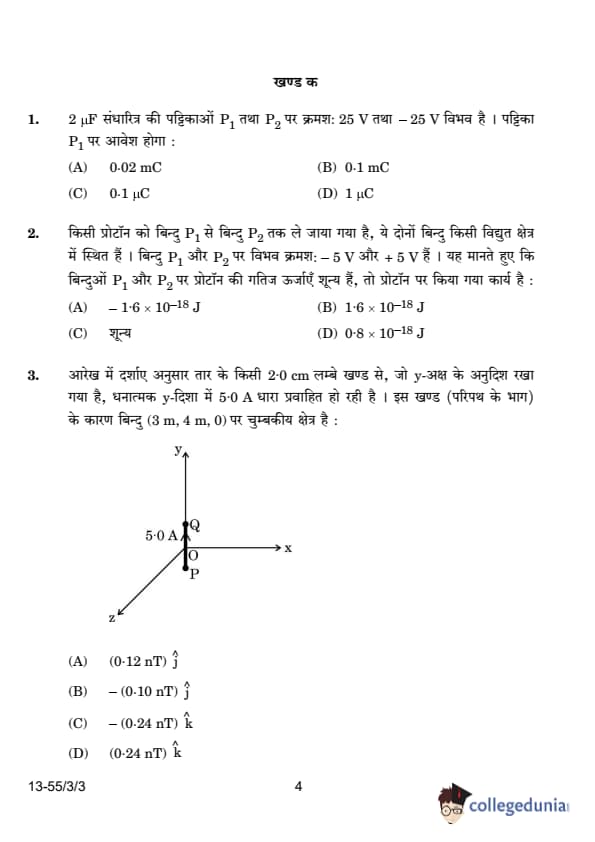
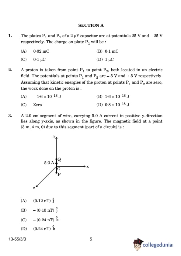
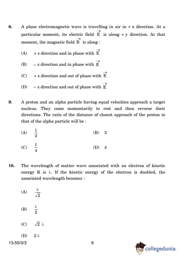
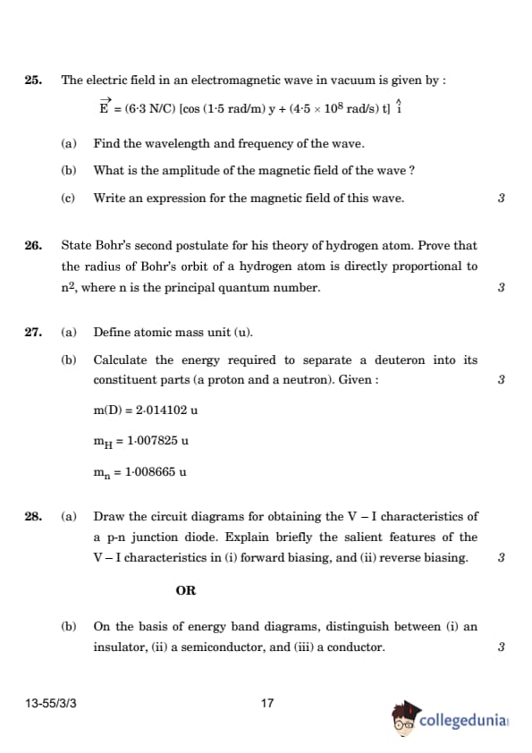
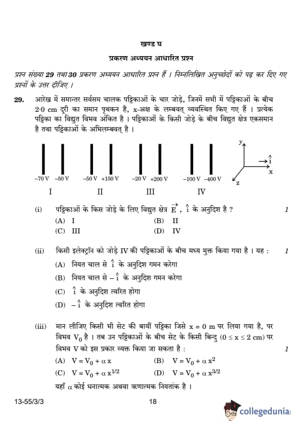
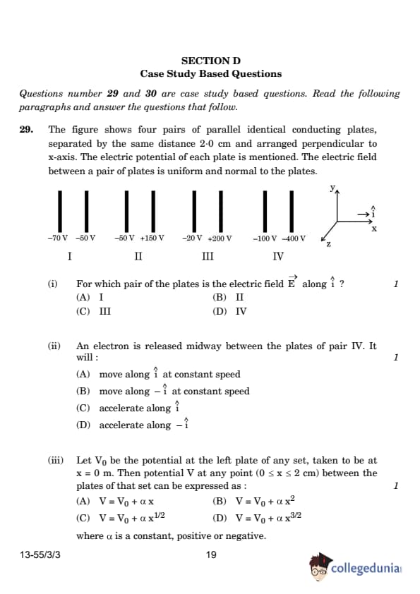
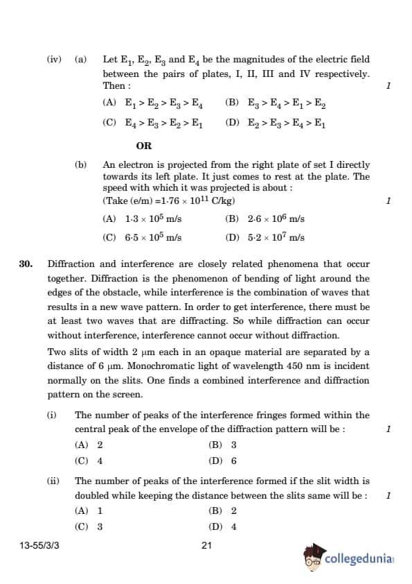
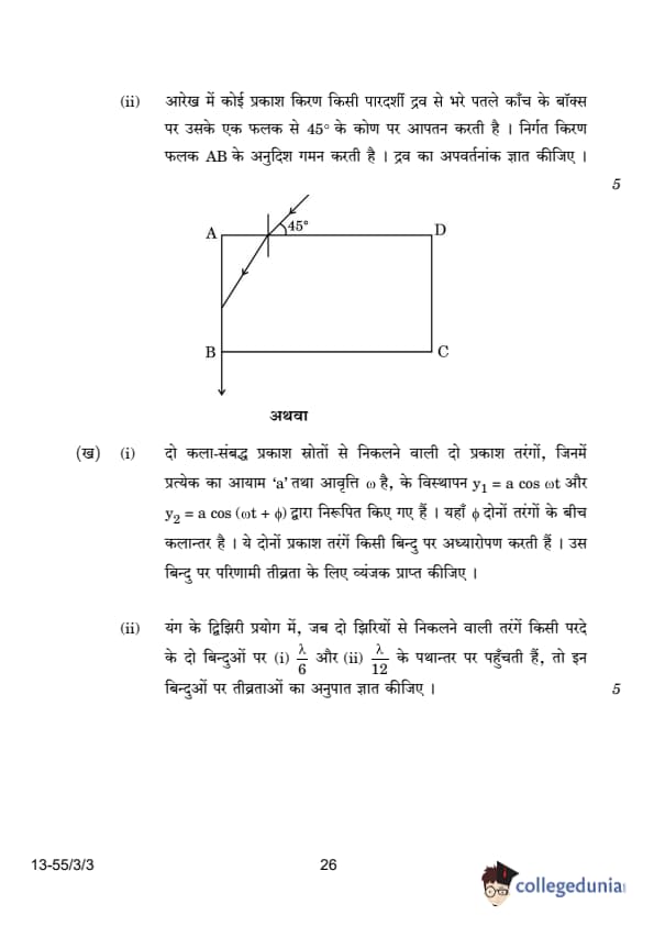
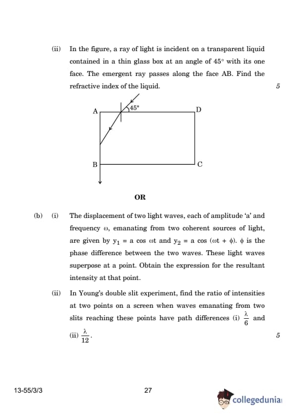


Comments