


CBSE Class 12 Physics Question Paper 2024 PDF (Set 3- 55/5/3) is available for download here. CBSE conducted the Physics exam on March 4, 2024, from 10:30 AM to 1:30 PM. The total marks for the theory paper are 70. The question paper contains 20% MCQ-based questions, 40% competency-based questions, and 40% short and long answer type questions. As per the students, the Physics exam was moderately difficult.
Candidates can use the link below to download the CBSE Class 12 Physics Set 3 Question Paper with detailed solutions.
CBSE Class 12 Physics Question Paper 2024 (Set 3- 55/5/3) with Answer Key
| CBSE Class 12 2024 Physics Question Paper with Answer Key | Check Solution |
CBSE Class Physics Questions with Solutions

A heater coil rated as \( (P, V) \) is cut into two equal parts. One of the parts is then connected to a battery of \( V \) volts. The power consumed by it will be:
View Solution
Step 1: Understanding the Problem.
The resistance of the original coil is given by: \[ R = \frac{V^2}{P}. \]
When the coil is cut into two equal parts, the resistance of each part becomes: \[ R_{new} = \frac{R}{2}. \]
Step 2: Calculating the New Power.
When one of the parts is connected to a battery of \( V \) volts, the power consumed is given by: \[ P_{new} = \frac{V^2}{R_{new}}. \]
Substituting \( R_{new} = \frac{R}{2} \): \[ P_{new} = \frac{V^2}{\frac{R}{2}} = 2 \cdot \frac{V^2}{R}. \]
From the original resistance \( R = \frac{V^2}{P} \), substitute \( R \): \[ P_{new} = 2P. \]
Final Answer: (D) \( 2P \) Quick Tip: Keep in mind that when resistance is halved, with voltage remaining constant, the power doubles. This occurs because of the inverse dependence of power on resistance.
Two insulated concentric coils, each of radius \( R \), placed at right angles to each other, carry currents \( I \) and \( \sqrt{3}I \), respectively. The magnitude of the net magnetic field at their common centre will be:
View Solution
Step 1: Magnetic field due to a single coil.
The magnetic field at the center of a circular coil carrying a current \( I \) is given by the equation: \[ B = \frac{\mu_0 I}{2R}. \]
For the first coil with current \( I \), the magnetic field at the center is: \[ B_1 = \frac{\mu_0 I}{2R}. \]
For the second coil with current \( \sqrt{3}I \), the field at the center becomes: \[ B_2 = \frac{\mu_0 (\sqrt{3}I)}{2R} = \frac{\sqrt{3} \mu_0 I}{2R}. \]
Step 2: Determining the resultant magnetic field.
Since the two coils are placed at right angles, the total magnetic field is found using the Pythagorean theorem: \[ B_{net} = \sqrt{B_1^2 + B_2^2}. \]
Substituting \( B_1 = \frac{\mu_0 I}{2R} \) and \( B_2 = \frac{\sqrt{3} \mu_0 I}{2R} \), we get: \[ B_{net} = \sqrt{\left( \frac{\mu_0 I}{2R} \right)^2 + \left( \frac{\sqrt{3} \mu_0 I}{2R} \right)^2}. \]
Simplifying: \[ B_{net} = \sqrt{\frac{\mu_0^2 I^2}{4R^2} + \frac{3\mu_0^2 I^2}{4R^2}} = \sqrt{\frac{4\mu_0^2 I^2}{4R^2}} = \frac{\mu_0 I}{R}. \]
Final Answer: (A) \( \frac{\mu_0 I}{R} \) Quick Tip: When calculating the resultant field from perpendicular vectors, apply the Pythagorean theorem: \( B_{net} = \sqrt{B_x^2 + B_y^2} \).
Which of the following materials has its magnetic susceptibility \( \chi \) in the range \( 0 < \chi < \epsilon \), where \( \epsilon \) is positive and small?
View Solution
To classify materials based on their magnetic susceptibility, we start by recognizing the general characteristics of magnetic susceptibility for different material types.
Paramagnetic materials exhibit a small positive value for magnetic susceptibility, i.e., \( \chi > 0 \). Examples include metals like aluminium.
Diamagnetic materials have a small negative magnetic susceptibility, i.e., \( \chi < 0 \). Water and bismuth are common examples of diamagnetic materials.
Ferromagnetic materials, such as gadolinium, have a large magnetic susceptibility that can vary with temperature, being paramagnetic above the Curie temperature.
Upon reviewing the materials provided:
Aluminium is clearly a paramagnetic material, which means it has a small positive magnetic susceptibility (\( \chi > 0 \)).
Water and bismuth are both diamagnetic, meaning they have a negative susceptibility (\( \chi < 0 \)).
Gadolinium becomes paramagnetic above its Curie temperature, so its susceptibility could range from positive to negative depending on temperature.
Therefore, the material with a magnetic susceptibility between \( 0 < \chi < \epsilon \) is aluminium.
Final Answer: (A) Aluminium Quick Tip: Remember that paramagnetic materials have a small positive susceptibility \( \chi > 0 \), while diamagnetic materials exhibit a small negative susceptibility \( \chi < 0 \). This classification can help in quickly identifying material types.
A galvanometer of resistance \( 100 \, \Omega \) gives full-scale deflection for a current of \( 1.0 \, mA \). It is converted into an ammeter of range \( 0 - 1 \, A \). The resistance of the ammeter will be close to:
View Solution
To convert a galvanometer into an ammeter, we need to connect a shunt resistance \( R_s \) in parallel with the galvanometer. This allows most of the current to bypass the galvanometer and flow through the shunt resistance.
The value of the shunt resistance can be determined using the formula: \[ R_s = \frac{I_g R_g}{I - I_g}, \]
where:
\( I_g = 1.0 \, mA \) is the current required for full-scale deflection of the galvanometer,
\( R_g = 100 \, \Omega \) is the resistance of the galvanometer,
\( I = 1 \, A \) is the maximum current that the ammeter should measure.
Substituting the given values into the formula: \[ R_s = \frac{(1.0 \times 10^{-3})(100)}{1 - 1.0 \times 10^{-3}} = \frac{0.1}{0.999}. \]
Simplifying: \[ R_s \approx 0.1 \, \Omega. \]
Thus, the value of the shunt resistance is \( 0.1 \, \Omega \).
Final Answer: (A) \( 0.1 \, \Omega \) Quick Tip: When converting a galvanometer into an ammeter, the shunt resistance formula \( R_s = \frac{I_g R_g}{I - I_g} \) helps determine the appropriate shunt value, ensuring the galvanometer remains protected while allowing the measurement of large currents.
The mutual inductance of two coils, in a given orientation, is \( 50 \, mH \). If the current in one of the coils changes as \( i = 1.0 \sin\left(100 \pi t + \frac{\pi}{3}\right) \, A \), the peak value of emf (in volts) induced in the other coil will be:
View Solution
The problem involves calculating the peak value of the electromotive force (emf) induced in the second coil due to a time-varying current in the first coil. We can use the formula for mutual inductance to solve it.
Formula for induced emf:
The induced emf \( \mathcal{E} \) in the second coil is related to the rate of change of the current in the first coil by:
\[ \mathcal{E} = -M \frac{di}{dt} \]
where:
\( M \) is the mutual inductance between the coils.
\( \frac{di}{dt} \) is the rate of change of the current in the first coil.
Step 1: Find the expression for the current \( i \) in the first coil
The given current is:
\[ i = 1.0 \sin\left(100 \pi t + \frac{\pi}{3}\right) \, A \]
Step 2: Differentiate the current with respect to time
To find \( \frac{di}{dt} \), differentiate the current expression:
\[ \frac{di}{dt} = \frac{d}{dt} \left( 1.0 \sin\left(100 \pi t + \frac{\pi}{3}\right) \right) \]
Using the chain rule:
\[ \frac{di}{dt} = 1.0 \cdot 100 \pi \cos\left(100 \pi t + \frac{\pi}{3}\right) \]
\[ \frac{di}{dt} = 100 \pi \cos\left(100 \pi t + \frac{\pi}{3}\right) \, A/s \]
Step 3: Find the peak value of the emf
The peak value of the induced emf occurs when \( \cos\left(100 \pi t + \frac{\pi}{3}\right) = 1 \) (because the maximum value of cosine is 1). Therefore, the peak emf is:
\[ \mathcal{E}_{peak} = M \cdot \left(100 \pi\right) \]
Substituting the value of the mutual inductance \( M = 50 \, mH = 50 \times 10^{-3} \, H \):
\[ \mathcal{E}_{peak} = (50 \times 10^{-3}) \cdot (100 \pi) \]
\[ \mathcal{E}_{peak} = 5 \pi \, V \]
Step 4: Conclusion
The peak emf induced in the second coil is \( 5 \pi \, V \).
Thus, the correct answer is:
\[ \boxed{(B) 5\pi} \] Quick Tip: For sinusoidal currents, the maximum rate of change of current \( \frac{di}{dt} \) is the product of the amplitude and the angular frequency \( A \omega \). Use this relation to quickly compute the induced emf.
The potential energy between two nucleons inside a nucleus is minimum at a distance of about:
View Solution
Step 1: Understanding nuclear potential energy.
Nucleons inside a nucleus interact through the nuclear force, which is attractive at small distances. The potential energy is minimized at the equilibrium separation, where the force changes from attraction to repulsion.
Step 2: Determining equilibrium separation.
The equilibrium separation between two nucleons is experimentally found to be approximately \( 0.8 \, fm \) (femtometers).
Final Answer: (A) \( 0.8 \, fm \) Quick Tip: In nuclear physics, the equilibrium distance between nucleons plays a crucial role in determining the binding energy and overall stability of the nucleus.
A pure Si crystal having \( 5 \times 10^{28} \, atoms/m^3 \) is doped with \( 1 \, ppm \) concentration of antimony. If the concentration of holes in the doped crystal is found to be \( 4.5 \times 10^9 \, m^{-3} \), the concentration (in \( m^{-3} \)) of intrinsic charge carriers in the Si crystal is about:
View Solution
Step 1: Carrier concentration in doped semiconductors.
In semiconductors that have been doped, the product of electron concentration (\( n_e \)) and hole concentration (\( n_h \)) remains constant: \[ n_e \cdot n_h = n_i^2, \]
where \( n_i \) represents the intrinsic carrier concentration.
Step 2: Substituting the known values.
Given: \[ n_h = 4.5 \times 10^9 \, m^{-3}, \quad n_e = donor concentration = 1 \, ppm \times 5 \times 10^{28}. \] \[ n_e = \frac{1}{10^6} \cdot 5 \times 10^{28} = 5 \times 10^{22} \, m^{-3}. \]
Step 3: Calculating the intrinsic carrier concentration (\( n_i \)).
\[ n_i = \sqrt{n_e \cdot n_h} = \sqrt{(5 \times 10^{22}) \cdot (4.5 \times 10^9)}. \] \[ n_i = \sqrt{2.25 \times 10^{32}} = 1.5 \times 10^{16} \, m^{-3}. \]
Final Answer: (B) \( 1.5 \times 10^{16} \) Quick Tip: In doped semiconductors, the relationship \( n_e \cdot n_h = n_i^2 \) is useful for connecting electron, hole, and intrinsic carrier concentrations.
The energy of an electron in the ground state of a hydrogen atom is \( -13.6 \, eV \). The kinetic and potential energy of the electron in the first excited state will be:
View Solution
Step 1: Energy in the first excited state.
The energy of an electron in the \( n \)-th orbit of a hydrogen atom is expressed as: \[ E_n = \frac{-13.6}{n^2} \, eV. \]
For the first excited state, where \( n = 2 \): \[ E_2 = \frac{-13.6}{2^2} = -3.4 \, eV. \]
Step 2: Relationships between kinetic and potential energy.
The kinetic energy (\( K.E. \)) is equal in magnitude but opposite in sign to the total energy: \[ K.E. = -E_2 = 3.4 \, eV. \]
The potential energy (\( P.E. \)) is twice the total energy: \[ P.E. = 2 \cdot E_2 = 2 \cdot (-3.4) = -6.8 \, eV. \]
Final Answer: (C) \( 3.4 \, eV, -6.8 \, eV \) Quick Tip: For hydrogen-like atoms, use the relations \( K.E. = -E_n \) and \( P.E. = 2E_n \). Always remember to substitute \( n^2 \) when calculating energy levels.
The electromagnetic waves used to purify water are:
View Solution
Step 1: The role of ultraviolet radiation in water purification.
Ultraviolet (UV) light has wavelengths ranging from \( 10 - 400 \, nm \) and possesses high energy, which makes it effective in neutralizing microorganisms, such as bacteria and viruses.
Step 2: Discarding other options.
Infrared radiation: Primarily used for heating, not for sterilization.
X-rays and gamma rays: Though highly penetrating, they are not commonly employed for water purification due to safety issues.
Final Answer: (B) Ultraviolet rays Quick Tip: Ultraviolet (UV) radiation is commonly used for water disinfection because it effectively damages the DNA of microorganisms.
The variation of the stopping potential (\( V_0 \)) with the frequency (\( \nu \)) of the incident radiation for four metals A, B, C, and D is shown in the figure. For the same frequency of incident radiation producing photoelectrons in all metals, the kinetic energy of photoelectrons will be maximum for metal:
View Solution
Step 1: Understanding the photoelectric equation and stopping potential.
The photoelectric equation is: \[ h\nu = \phi + K.E., \]
where:
\( h\nu \) is the energy of the incoming photon,
\( \phi \) is the work function of the metal,
\( K.E. \) is the kinetic energy of the emitted photoelectron.
The stopping potential (\( V_0 \)) is related to the kinetic energy of the emitted electron by: \[ K.E. = eV_0, \]
where \( e \) is the electron charge.
Step 2: Interpreting the graph.
The graph shows how the stopping potential \( V_0 \) varies with the frequency \( \nu \) for different metals. The slope of each line indicates \( \frac{h}{e} \), which remains constant across all metals, and the x-intercept corresponds to the threshold frequency (\( \nu_0 \)) for each metal.
Metals with a lower threshold frequency (\( \nu_0 \)) have a smaller work function (\( \phi = h\nu_0 \)), leading to higher kinetic energy for the emitted electrons when exposed to the same incident frequency (\( \nu \)).
Step 3: Determining the metal with the maximum kinetic energy.
From the graph, metal A has the lowest threshold frequency (\( \nu_0 \)), meaning it has the smallest work function (\( \phi \)). Therefore, for the same incident frequency, metal A will produce photoelectrons with the greatest kinetic energy.
Final Answer: (A) A Quick Tip: For photoelectric effects, the metal with the lowest threshold frequency will emit electrons with the highest kinetic energy when exposed to the same photon frequency.
The focal lengths of the objective and the eyepiece of a compound microscope are \( 1 \, cm \) and \( 2 \, cm \), respectively. If the tube length of the microscope is \( 10 \, cm \), the magnification obtained by the microscope for most suitable viewing by relaxed eye is:
View Solution
Step 1:
The focal lengths of the objective and the eyepiece of a compound microscope are 1 cm and 2 cm respectively. The tube length of the microscope is 10 cm, and the magnification obtained by the microscope for most suitable viewing by the relaxed eye is 125.
Explanation:
For the eyepiece:
\[ \frac{1}{f_e} = \frac{1}{v_e} - \frac{1}{u_e} \]
\[ \frac{1}{2} = \frac{1}{-25} - \frac{1}{u_e} \]
\[ \Rightarrow u_e = -1.85 \, cm \]
Since the length of the pipe is 10 cm, we have:
\[ |v_o| + |u_e| = 10 \, cm \]
\[ \Rightarrow |v_o| = 10 + (-1.85) = 8.15 \, cm \]
For the objective lens:
\[ \frac{1}{f_o} = \frac{1}{v_o} - \frac{1}{u_o} \]
\[ \frac{1}{1} = \frac{1}{8.15} - \frac{1}{u_o} \]
\[ \Rightarrow u_o = -0.877 \, cm \]
Now, magnification:
\[ m = \frac{v_o}{|u_o|} \left(1 + \frac{D}{f_e}\right) \]
\[ m = \frac{8.15}{0.877} \left(1 + \frac{25}{2}\right) \]
\[ m = 125.46 \approx 125 \]
Final Answer: (d) 125 Quick Tip: To calculate the total magnification of a compound microscope for relaxed-eye viewing, use \( M = \frac{L}{f_o} \cdot \left(1 + \frac{D}{f_e}\right) \). Remember that the standard value for \( D = 25 \, cm \).
A point object is kept \( 60 \, cm \) in front of a spherical convex surface (\( n = 1.5 \), radius of curvature \( 40 \, cm \)). The image formed is:
View Solution
Step 1: Using the formula for refraction at a spherical surface.
The formula is: \[ \frac{\mu_2}{v} - \frac{\mu_1}{u} = \frac{\mu_2 - \mu_1}{R} \]
where:
\( \mu_1 = 1.0 \) (refractive index of air),
\( \mu_2 = 1.5 \) (refractive index of the medium),
\( \mu = -60 \, cm \) (object distance, negative as it is in front of the surface),
\( R = 40 \, cm \) (radius of curvature).
Step 2: Substituting the given values:
\[ \frac{1.5}{v} - \frac{1}{-60} = \frac{1.5 - 1}{40} \]
Simplifying:
\[ \frac{1.5}{v} + \frac{1}{60} = \frac{0.5}{40} \]
\[ \frac{1.5}{v} = \frac{1}{80} - \frac{1}{60} \]
Finding the common denominator:
\[ \frac{1.5}{v} = \frac{3}{240} - \frac{4}{240} \]
\[ \frac{1.5}{v} = \frac{-1}{240} \]
Now, solving for \( v \):
\[ v = -240 \times \frac{15}{10} = -360 \, cm = -3.6 \, m \]
Since the image distance \( v \) is negative, it indicates that the image formed is virtual.
Conclusion: The image formed is virtual and at a distance of \( 3.6 \, m \). Quick Tip: For refraction at a spherical surface, use the formula \( \frac{n_2}{v} - \frac{n_1}{u} = \frac{n_2 - n_1}{R} \) carefully, ensuring consistent sign conventions for distances.
Assertion (A): In a Young’s double-slit experiment, interference pattern is not observed when two coherent sources are infinitely close to each other.
Reason (R): The fringe width is proportional to the separation between the two sources.
(A) If both Assertion (A) and Reason (R) are true and Reason (R) is the correct explanation
of Assertion (A).
(B) If both Assertion (A) and Reason (R) are true and Reason (R) is not the correct
explanation of Assertion (A).
(C) If Assertion (A) is true but Reason (R) is false.
(D) If both Assertion (A) and Reason (R) are false.
View Solution
Step 1: Evaluating Assertion (A).
Assertion (A) is correct because when the two coherent sources are brought infinitely close together, the fringe width increases significantly, causing the interference pattern to become essentially unobservable.
Step 2: Evaluating Reason (R).
Reason (R) is incorrect because the fringe width in Young's double-slit experiment is inversely proportional to the separation between the two sources, not directly proportional.
Final Answer: (C) Assertion (A) is true, but Reason (R) is false. Quick Tip: In Young's double-slit experiment, the fringe width \( \beta \) is calculated using \( \beta = \frac{\lambda D}{d} \), where \( \lambda \) is the wavelength of light, \( D \) is the distance to the screen, and \( d \) is the distance between the slits.
Assertion (A): An alpha particle is moving towards a gold nucleus. The impact parameter is maximum for the scattering angle of \( 180^\circ \).
Reason (R): The impact parameter in an alpha particle scattering experiment does not depend upon the atomic number of the target nucleus.
(A) If both Assertion (A) and Reason (R) are true and Reason (R) is the correct explanation
of Assertion (A).
(B) If both Assertion (A) and Reason (R) are true and Reason (R) is not the correct
explanation of Assertion (A).
(C) If Assertion (A) is true but Reason (R) is false.
(D) If both Assertion (A) and Reason (R) are false.
View Solution
Assertion (A): The impact parameter is the perpendicular distance between the trajectory of the incoming alpha particle and the center of the target nucleus. For the scattering angle \( \theta = 180^\circ \), which corresponds to a backscattering event, the impact parameter is actually the minimum distance at which the alpha particle would just graze the nucleus. Hence, the assertion that the impact parameter is maximum for a scattering angle of \( 180^\circ \) is incorrect. For maximum impact parameter, the scattering angle should be \( 90^\circ \), not \( 180^\circ \).
Reason (R): The impact parameter does depend upon the atomic number \( Z \) of the target nucleus. The Coulomb force between the alpha particle and the nucleus is proportional to \( Z \), so a higher atomic number will influence the scattering and the impact parameter. Hence, the reason that the impact parameter does not depend on the atomic number is false.
Thus, both Assertion (A) and Reason (R) are false. Quick Tip: In alpha particle scattering, the impact parameter is related to the scattering angle. For backscattering (angle \( 180^\circ \)), the impact parameter is minimum, not maximum. Additionally, the impact parameter depends on the atomic number \( Z \) of the target nucleus.
Assertion (A): Equal amount of positive and negative charges are distributed uniformly on two halves of a thin circular ring as shown in the figure. The resultant electric field at the centre \( O \) of the ring is along \( OC \).
Reason (R): It is so because the net potential at \( O \) is not zero.
(A) If both Assertion (A) and Reason (R) are true and Reason (R) is the correct explanation
of Assertion (A).
(B) If both Assertion (A) and Reason (R) are true and Reason (R) is not the correct
explanation of Assertion (A).
(C) If Assertion (A) is true but Reason (R) is false.
(D) If both Assertion (A) and Reason (R) are false.
View Solution
Step 1: Evaluating Assertion (A).
The positive charges on the top half and the negative charges on the bottom half produce an electric field at the center \( O \). Due to symmetry, the horizontal components of the electric field cancel each other, and the resulting electric field points vertically along \( OC \). Therefore, Assertion (A) is correct.
Step 2: Evaluating Reason (R).
The potential at \( O \) is the sum of the potentials from the positive and negative charges. Since the charge distributions are symmetric and of equal magnitude, the total potential at \( O \) is zero. Thus, Reason (R) is incorrect.
Final Answer: (C) Assertion (A) is true, but Reason (R) is false. Quick Tip: When dealing with symmetric charge distributions, remember to treat electric fields as vectors and electric potentials as scalars to correctly analyze the system.
Assertion (A): The energy of a charged particle moving in a magnetic field does not change.
Reason (R): It is because the work done by the magnetic force on the charge moving in a magnetic field is zero.
(A) If both Assertion (A) and Reason (R) are true and Reason (R) is the correct explanation
of Assertion (A).
(B) If both Assertion (A) and Reason (R) are true and Reason (R) is not the correct
explanation of Assertion (A).
(C) If Assertion (A) is true but Reason (R) is false.
(D) If both Assertion (A) and Reason (R) are false.
View Solution
Step 1: Evaluating Assertion (A).
The magnetic force on a charged particle always acts perpendicular to its velocity. As a result, it cannot perform work on the particle, meaning the kinetic energy (and total energy) of the particle remains constant. Therefore, Assertion (A) is correct.
Step 2: Evaluating Reason (R).
The work done by a force is given by: \[ W = \vec{F} \cdot \vec{d} = F d \cos \theta, \]
where \( \theta \) is the angle between the force and displacement. For the magnetic force, \( \theta = 90^\circ \), so the work done is \( W = 0 \). This explains why the energy of the charged particle does not change. Therefore, Reason (R) is true and provides the correct explanation for Assertion (A).
Final Answer: (A) Both Assertion (A) and Reason (R) are true, and Reason (R) is the correct explanation of Assertion (A). Quick Tip: The magnetic force does no work on a charged particle because it acts perpendicular to the velocity, which preserves the particle's kinetic energy.
Derive an expression for magnetic force \( \vec{F} \) acting on a straight conductor of length \( L \) carrying current \( I \) in an external magnetic field \( \vec{B} \). Is it valid when the conductor is in zig-zag form? Justify.
View Solution
Step 1: Magnetic force on a current-carrying conductor.
When a conductor of length \( L \) carrying a current \( I \) is placed in a magnetic field \( \vec{B} \), the magnetic force \( \vec{F} \) acting on the conductor is given by: \[ \vec{F} = I (\vec{L} \times \vec{B}), \]
where \( \vec{L} \) is the vector representing the length of the conductor in the direction of the current, and \( \times \) denotes the cross product between the two vectors.
Step 2: Derivation of the force.
For a small element \( d\vec{l} \) of the conductor, the magnetic force is: \[ d\vec{F} = I (d\vec{l} \times \vec{B}). \]
Integrating over the entire length of the conductor: \[ \vec{F} = \int I (d\vec{l} \times \vec{B}) = I (\vec{L} \times \vec{B}), \]
where \( \vec{L} = \int d\vec{l} \) represents the total length vector of the conductor.
Step 3: Validity for a zig-zag conductor.
For a zig-zag-shaped conductor, the magnetic force on each segment can be computed individually. The total force is the vector sum of the forces on all the individual segments. Since the magnetic force depends only on the net length vector \( \vec{L} \), the derived expression remains valid even for a zig-zag conductor.
Final Expression: \[ \vec{F} = I (\vec{L} \times \vec{B}) \] Quick Tip: The magnetic force on a current-carrying conductor depends on the total length vector \( \vec{L} \), not the specific shape of the conductor. For non-linear shapes, ensure \( \vec{L} \) is calculated correctly.
(a) Four point charges of \( 1 \, \muC, -2 \, \muC, 1 \, \muC, \) and \( -2 \, \muC \) are placed at the corners \( A, B, C, \) and \( D \), respectively, of a square of side \( 30 \, cm \). Find the net force acting on a charge of \( 4 \, \muC \) placed at the centre of the square.
View Solution

Step 1: Charge configuration and symmetry.
The charges \( +1 \, \muC \) and \( -2 \, \muC \) are placed symmetrically about the center. Let the side of the square be \( a = 30 \, cm = 0.3 \, m \). The distance from the center to each corner is: \[ r = \frac{a}{\sqrt{2}} = \frac{0.3}{\sqrt{2}} = 0.212 \, m. \]
Step 2: Force on the central charge.
The force exerted by a charge \( q_i \) on the central charge \( q = 4 \, \muC \) is: \[ F_i = \frac{k |q_i q|}{r^2}, \]
where \( k = 9 \times 10^9 \, N·m^2/C^2 \). Substituting \( r = 0.212 \, m \):
\[ F_{OA} = F_{OC} = \frac{9 \times 10^9 \times 4 \times 10^{-6} \times 1 \times 10^{-6}}{(15\sqrt{2} \times 10^{-2})^2} = 0.8 \, N \]
\[ F_{OB} = F_{OD} = 1.6 \, N \]
\[ F_1 = F_{OA} - F_{OC} = 0 \]
\[ F_2 = F_{OB} - F_{OD} = 0 \]
Step 3: Superposition of forces.
Due to symmetry, the forces from opposite charges cancel out along both the horizontal and vertical directions. As a result, the net force on the central charge is zero: \[ F_{net} = 0. \] Quick Tip: In symmetric charge configurations, use the principles of symmetry and vector addition to recognize when forces cancel out, leading to a net force of zero.
(b) Three point charges, \( 1 \, pC \) each, are kept at the vertices of an equilateral triangle of side \( 10 \, cm \). Find the net electric field at the centroid of the triangle.
View Solution

Given:
\( q_A = q_B = q_C = 1 \, C \)
\( AO = BO = CO = r \)
Electric Field at Point A:
The magnitudes of the electric fields at points \( A \), \( B \), and \( C \) are the same, so we have:
\[ \left| \vec{E}_{OA} \right| = \left| \vec{E}_{OB} \right| = \left| \vec{E}_{OC} \right| \]
\[ \vec{E}_{BC} = \vec{E}_{OB} + \vec{E}_{OC} \]
Electric Field at Point B and C:
Using the vector sum, we can find the magnitude of the resultant electric field at point \( B \) and \( C \) using the cosine rule:
\[ \vec{E}_{BC} = \sqrt{E_{OB}^2 + E_{OC}^2 + 2E_{OB}E_{OC} \cos(120^\circ)} \]
Since \( \vec{E}_{OA} = -\vec{E}_{BC} \), we have:
\[ \vec{E}_{BC} = E_{OB}, \quad \vec{E}_{OA} = -\vec{E}_{BC} \]
Net Electric Field:
The net electric field \( \vec{E}_O \) is the vector sum of \( \vec{E}_{OA} \) and \( \vec{E}_{BC} \):
\[ \vec{E}_O = \vec{E}_{OA} + \vec{E}_{BC} \]
Since \( \vec{E}_O = 0 \), the net electric field at point \( O \) is zero. Quick Tip: In symmetric charge distributions, simplify calculations by analyzing the net effect along axes and using trigonometric identities.
A thin converging lens of focal length \( 10 \, cm \) is placed coaxially in contact with a thin diverging lens of focal length \( 15 \, cm \). How will the combination behave? Justify your answer.
View Solution
Step 1: Formula for the focal length of the lens combination.
The equivalent focal length (\( f \)) for two lenses placed in contact is given by the formula: \[ \frac{1}{f} = \frac{1}{f_1} + \frac{1}{f_2}, \]
where \( f_1 = +10 \, cm \) is the focal length of the converging lens and \( f_2 = -15 \, cm \) is the focal length of the diverging lens.
Step 2: Substituting the given values.
\[ \frac{1}{f} = \frac{1}{10} + \frac{1}{-15} = \frac{3}{30} - \frac{2}{30} = \frac{1}{30}. \]
Thus, \[ f = 30 \, cm. \]
Step 3: Behavior of the lens combination.
Since the equivalent focal length is positive, the combined lens system behaves as a converging lens with an effective focal length of \( 30 \, cm \).
Final Answer: The combination behaves as a converging lens with a focal length of \( 30 \, cm \). Quick Tip: When combining two lenses in contact, use the formula \( \frac{1}{f} = \frac{1}{f_1} + \frac{1}{f_2} \) to find the equivalent focal length. A positive result indicates a converging lens.
Deuterium undergoes the following fusion reaction: \[ {}^2_1H + {}^2_1H \rightarrow {}^3_2He + {}^1_0n + 3.27 \, MeV. \]
How long an electric bulb of \( 200 \, W \) will glow by using the energy released in \( 2 \, g \) of deuterium?
View Solution
Step 1: Energy released per fusion reaction.
The energy released by each fusion reaction is \( 3.27 \, MeV \). To convert this into joules: \[ 1 \, MeV = 1.6 \times 10^{-13} \, J, \quad so \quad 3.27 \, MeV = 3.27 \times 1.6 \times 10^{-13} = 5.23 \times 10^{-13} \, J. \]
Step 2: Determining the number of deuterium nuclei in \( 2 \, g \).
The molar mass of deuterium is \( 2 \, g/mol \), meaning that \( 2 \, g \) contains: \[ N = \frac{2}{2} \times 6.022 \times 10^{23} = 6.022 \times 10^{23} \, nuclei. \]
Step 3: Calculating the total energy released.
Since each fusion reaction involves two deuterium nuclei, the total number of reactions is: \[ Reactions = \frac{6.022 \times 10^{23}}{2} = 3.011 \times 10^{23}. \]
Thus, the total energy released is: \[ E = 3.011 \times 10^{23} \times 5.23 \times 10^{-13} = 1.57 \times 10^{11} \, J. \]
Step 4: Determining the time for the bulb to glow.
Given that the power of the bulb is \( P = 200 \, W \), the time \( t \) required for the bulb to glow is: \[ t = \frac{E}{P} = \frac{1.57 \times 10^{11}}{200} = 7.85 \times 10^8 \, s. \]
Converting this time to years: \[ t = \frac{7.85 \times 10^8}{60 \times 60 \times 24 \times 365} \approx 25 \, years. \]
Final Answer: The bulb will glow for approximately \( 25 \, years \). Quick Tip: Ensure that energy units are consistently converted and always factor in the stoichiometry of the reaction when calculating the total energy released.
The electron in a hydrogen atom is revolving with a speed of \( 2.2 \times 10^6 \, m/s \) in an orbit of radius \( 0.53 \, Å \). Calculate the initial frequency of light emitted by the electron using classical physics.
View Solution
Given:
The formula for the frequency \( v \) of a charged particle in circular motion is given by:
\[ v = \frac{v}{2 \pi r} \]
where:
\( v = 2.2 \times 10^6 \, m/s \) is the velocity of the particle,
\( r = 0.53 \times 10^{-10} \, m \) is the radius of the orbit.
Step-by-Step Calculation:
Substituting the given values into the formula:
\[ v = \frac{2.2 \times 10^6}{2 \pi \times 0.53 \times 10^{-10}} \]
Now, simplify the denominator:
\[ v = \frac{2.2 \times 10^6}{2 \times \pi \times 0.53 \times 10^{-10}} \]
First, calculate the denominator:
\[ 2 \times \pi \times 0.53 \times 10^{-10} \approx 3.33 \times 10^{-10} \]
Now, divide the numerator by the denominator:
\[ v = \frac{2.2 \times 10^6}{3.33 \times 10^{-10}} = 6.6 \times 10^{15} \, Hz \]
Thus, the frequency is:
\[ v = 6.6 \times 10^{15} \, Hz \] Quick Tip: In classical physics, the frequency of emitted light corresponds to the frequency of revolution of the electron, calculated as \( f = \frac{v}{2 \pi r} \).
State Lenz’s Law. In a closed circuit, the induced current opposes the change in magnetic flux that produced it as per the law of conservation of energy. Justify.
View Solution
Lenz's Law:
Lenz's Law states that the direction of the induced current in a closed loop will always oppose the change in magnetic flux that caused it.
Explanation:
This law directly follows from the principle of conservation of energy. If the induced current were to support the change in flux, it would result in an endless increase in flux without requiring external energy, which would violate the conservation of energy. The opposing direction of the induced current ensures that energy is required to alter the flux, maintaining energy conservation. Quick Tip: Lenz’s Law helps maintain energy conservation and determines the direction of the induced current. Use the right-hand rule to accurately find the direction of the induced current.
A metal rod of length \( 2 \, m \) is rotated with a frequency \( 60 \, rev/s \) about an axis passing through its centre and perpendicular to its length. A uniform magnetic field of \( 2 \, T \), perpendicular to its plane of rotation, is switched-on in the region. Calculate the e.m.f. induced between the centre and the end of the rod.
View Solution
Step 1: Formula for the induced e.m.f.
The induced e.m.f. (\( \epsilon \)) in a rod rotating within a magnetic field is given by the equation: \[ \epsilon = \frac{1}{2} B \omega L^2, \]
where:
\( B = 2 \, T \) is the magnetic field strength,
\( L = 2 \, m \) is the length of the rod,
\( \omega = 2\pi f \) is the angular velocity, and
\( f = 60 \, rev/s \) is the frequency of rotation.
Step 2: Calculating angular velocity \( \omega \).
\[ \omega = 2\pi f = 2\pi \times 60 = 120\pi \, rad/s. \]
Step 3: Substituting the known values.
\[ \frac{1}{2} \times 2 \times (2)^2 \times (2 \pi \times 60) \]
\[ = 480 \pi \, V \]
\[ = 1.51 \times 10^3 \, V \]
Step 4: Final calculation.
\[ = 1.51 \times 10^3 \, V \]
Final Answer: The induced e.m.f. is approximately \[ = 1.51 \times 10^3 \, V \]. Quick Tip: For rotating rods in a magnetic field, use the formula \( \epsilon = \frac{1}{2} B \omega L^2 \). Make sure angular velocity \( \omega \) is expressed in radians per second.
State and explain Ampere’s circuital law.
View Solution
Ampere’s Circuital Law:
Ampere’s Circuital Law states that the line integral of the magnetic field \( \vec{B} \) around a closed loop is equal to \( \mu_0 \) multiplied by the total enclosed current \( I_{enc} \): \[ \oint \vec{B} \cdot d\vec{l} = \mu_0 I_{enc}. \]
Explanation:
This law establishes the relationship between the circulation of the magnetic field and the current that passes through a loop. It is particularly useful when calculating \( \vec{B} \) in situations with high symmetry, such as for long straight wires, solenoids, or toroids. Quick Tip: Apply Ampere’s law to symmetric current distributions. Make sure to choose a path that completely encloses the current for accurate calculations.
Two long straight parallel wires separated by \( 20 \, cm \), carry \( 5 \, A \) and \( 10 \, A \) current respectively, in the same direction. Find the magnitude and direction of the net magnetic field at a point midway between them.
View Solution
Given:
The formula for the magnetic field due to a long straight conductor carrying current \( I \) at a distance \( r \) from the conductor is given by:
\[ B = \frac{\mu_0 I}{2 \pi r} \]
where:
\( \mu_0 \) is the permeability of free space,
\( I \) is the current in the conductor,
\( r \) is the distance from the wire where the magnetic field is being calculated.
Net Magnetic Field Calculation:
The net magnetic field at a point due to two magnetic fields \( B_2 \) and \( B_1 \) is given by the difference between the two fields:
\[ B = B_2 - B_1 \]
Substitute the expression for \( B \) from the formula for each of the magnetic fields:
\[ B = \frac{\mu_0 \times 10^2}{20 \pi} \times [10 - 5] \]
Simplify the expression inside the brackets:
\[ B = \frac{\mu_0 \times 10^2}{20 \pi} \times 5 \]
Substitute \( \mu_0 = 4 \pi \times 10^{-7} \) in the expression:
\[ B = \frac{4 \pi \times 10^{-7} \times 10^2 \times 5}{20 \pi} \]
Simplify the expression:
\[ B = \frac{4 \times 10^{-7} \times 10^2 \times 5}{20} \]
Now, cancel the \( \pi \) terms and simplify further:
\[ B = 10^{-5} \, T \]
Thus, the magnetic field at the point is:
\[ B = 10^{-5} \, T \]
Direction of Magnetic Field:
The magnetic field is directed along the direction of the magnetic field produced by the conductor carrying a current of 10 A. Quick Tip: When dealing with two parallel currents, the magnetic fields at the midpoint subtract if the currents are in the same direction and add if they are in opposite directions.
The threshold frequency for a metal is \( 3.0 \times 10^{14} \, Hz \). A beam of frequency \( 9.0 \times 10^{14} \, Hz \) is incident on the metal. Calculate (i) the work function (in eV) of the metal and (ii) the maximum speed of photoelectrons.
View Solution
(i) Work function calculation:
The work function \( \phi_0 \) is given by the equation:
\[ \phi_0 = h v_0 \]
where:
\( h = 6.63 \times 10^{-34} \, J \cdot s \) is Planck's constant,
\( v_0 = 3.0 \times 10^{14} \, Hz \) is the frequency of the light.
Substituting the values:
\[ \phi_0 = \frac{6.63 \times 10^{-34} \times 3.0 \times 10^{14}}{1.6 \times 10^{-19}} \]
Now, simplify the expression:
\[ \phi_0 = 1.24 \, eV \]
Thus, the work function is:
\[ \phi_0 = 1.24 \, eV \]
(ii) Maximum Kinetic Energy and Maximum Velocity:
The maximum kinetic energy \( K_{max} \) of the emitted electron is given by the equation:
\[ K_{max} = h v - h v_0 \]
Using the equation for kinetic energy in terms of velocity:
\[ \frac{1}{2} m V_{max}^2 = h (v - v_0) \]
Solving for the maximum velocity \( V_{max} \):
\[ V_{max} = \left( \frac{2 h (v - v_0)}{m} \right)^{\frac{1}{2}} \]
Substitute the values:
\[ V_{max} = \left( \frac{2 \times 6.63 \times 10^{-34} \times (9 - 3) \times 10^{14}}{9.1 \times 10^{-31}} \right)^{\frac{1}{2}} \]
Simplifying:
\[ V_{max} = \left( \frac{2 \times 6.63 \times 10^{-34} \times 6 \times 10^{14}}{9.1 \times 10^{-31}} \right)^{\frac{1}{2}} = 9.35 \times 10^5 \, m/s \]
Thus, the maximum velocity of the emitted electron is:
\[ V_{max} = 9.35 \times 10^5 \, m/s \] Quick Tip: The work function is calculated using \( \phi = h f_{th} \), and the kinetic energy of photoelectrons is \( K.E_{max} = h f - \phi \). Always convert energy into the desired unit (J or eV) for clarity.
(a) Name the parts of the electromagnetic spectrum which are (i) also known as ‘heat waves’ and (ii) absorbed by the ozone layer in the atmosphere.
View Solution
(i) Infrared waves: These waves are often referred to as heat waves because they are primarily responsible for the radiation of heat.
(ii) Ultraviolet waves: These waves are absorbed by the ozone layer in the atmosphere, which acts as a shield, protecting life on Earth from harmful UV radiation. Quick Tip: Infrared waves are commonly used for heat sensing and thermal imaging, while ultraviolet waves play a crucial role in sterilization and are absorbed by the ozone layer for protection.
(b) Write briefly one method each, of the production and detection of these radiations.
View Solution
(i) Infrared waves:
Production: Generated by hot objects or when electric currents pass through resistive materials.
Detection: Detected using thermopiles, bolometers, or infrared cameras.
(ii) Ultraviolet waves:
Production: Produced by high-energy processes, such as electric discharges in gases or blackbody radiation from hot objects.
Detection: Detected using photodiodes, UV-sensitive films, or spectrophotometers. Quick Tip: Electromagnetic waves are produced and detected using different methods depending on their energy and wavelength. Infrared waves typically require heat-sensitive detectors, while ultraviolet waves are detected using photodetectors.
(a) Explain the characteristics of a p-n junction diode that makes it suitable for its use as a rectifier.
View Solution
A p-n junction diode has key characteristics that make it ideal for use as a rectifier:
1. Unidirectional Conductivity: The p-n junction diode allows current to flow only when forward biased, permitting current flow in a single direction.
2. Reverse Blocking: When reverse biased, the diode blocks current, preventing any backflow in a rectifier circuit.
3. Non-linear I-V Characteristics: The exponential increase in current under forward bias ensures efficient conduction during the positive half-cycle of an AC input signal. Quick Tip: The rectification process relies on the diode’s ability to conduct current in one direction and block it in the reverse direction. Proper biasing is essential for efficient rectification.
(b) With the help of a circuit diagram, explain the working of a full-wave rectifier.
View Solution
Step 1: Circuit diagram of a full-wave rectifier.
A full-wave rectifier consists of:
A center-tapped transformer,
Two diodes (\( D_1 \) and \( D_2 \)),
A load resistor (\( R_L \)).

Step 2: Operation.
1. During the positive half-cycle of the AC input, diode \( D_1 \) conducts, allowing current to flow through \( R_L \). Diode \( D_2 \) remains reverse-biased.
2. During the negative half-cycle, diode \( D_2 \) conducts, allowing current to flow through \( R_L \) in the same direction. Diode \( D_1 \) remains reverse-biased.
3. The output across \( R_L \) produces a rectified (unidirectional) voltage. Quick Tip: The full-wave rectifier offers higher efficiency compared to a half-wave rectifier because it utilizes both halves of the AC input signal, resulting in a smoother output.
Explain the following giving reasons:
(a) A doped semiconductor is electrically neutral. Explain.
View Solution
A doped semiconductor remains electrically neutral because:
1. During doping, donor or acceptor atoms are introduced, which either donate or accept electrons, but the overall charge of the material stays balanced.
2. The number of positive and negative charges (nuclei and electrons/holes) remains equal, maintaining electrical neutrality. Quick Tip: Doping alters the electrical characteristics of a semiconductor, but it does not change its overall charge neutrality.
In a p-n junction under equilibrium, there is no net current. Explain.
View Solution
At equilibrium:
1. The diffusion current, which arises from the concentration gradient of charge carriers, is balanced by the drift current caused by the electric field in the depletion region.
2. These opposing currents cancel out, resulting in no net current flowing across the junction. Quick Tip: Equilibrium in a p-n junction occurs when the drift and diffusion currents are balanced, leading to zero net current.
(c) In a diode, the reverse current is practically not dependent on the applied voltage. Explain.
View Solution
In reverse bias:
1. Reverse Current Due to Minority Carriers:
When a diode is reverse-biased, the majority charge carriers (electrons in the n-region and holes in the p-region) are pulled away from the junction, widening the depletion region. However, a small current still flows due to minority charge carriers, which are thermally generated in both the p- and n-regions.
These minority carriers are few in number and have negligible effect under normal conditions, leading to a very small reverse current, called the reverse saturation current (\( I_{reverse} \)).
The reverse current is thermally generated and is largely independent of the applied reverse voltage, as long as the voltage does not exceed a critical threshold called the breakdown voltage.
2. Reverse Current Characteristics:
As long as the applied reverse voltage does not exceed the diode’s breakdown voltage, the reverse current remains constant. This constant current is the result of minority carriers moving through the junction.
The reverse current is primarily dependent on temperature: as the temperature increases, more minority carriers are thermally generated, which leads to an increase in the reverse current.
If the reverse voltage exceeds the breakdown voltage, the diode undergoes avalanche breakdown or Zener breakdown (depending on the type of diode), causing a sharp increase in reverse current.
Final Answer: The reverse current in a diode is primarily due to minority carriers and is temperature-dependent. It remains constant as long as the applied voltage does not exceed the breakdown voltage. Quick Tip: The reverse current in a diode is mainly determined by temperature and is independent of the reverse voltage until the breakdown voltage is reached.
An electron is moving with a velocity \[ \vec{v} = \left( 3 \times 10^6 \, \frac{m}{s} \right) \hat{i} \]
It enters a region of magnetic field \[ \vec{B} = (91 \, mT) \hat{k}. \]
(a) Calculate the magnetic force \( \vec{F}_B \) acting on an electron and the radius of its path.
View Solution
Step 1: Magnetic force on the electron.
The magnetic force acting on the electron is given by: \[ \vec{F}_B = q (\vec{v} \times \vec{B}), \]
where:
\( q = -1.6 \times 10^{-19} \, C \) is the charge of the electron,
\( \vec{v} = 3 \times 10^6 \, \hat{i} \, m/s \) is the velocity of the electron,
\( \vec{B} = 91 \, mT \, \hat{k} = 91 \times 10^{-3} \, \hat{k} \, T \) is the magnetic field.
The magnitude of the magnetic force is calculated as: \[ F_B = q v B \sin\theta = (1.6 \times 10^{-19})(3 \times 10^6)(91 \times 10^{-3})(\sin 90^\circ). \] \[ F_B = 4.37 \times 10^{-14} \, N. \]
Step 2: Radius of the circular path.
The radius of the circular path followed by the electron is given by: \[ r = \frac{m v}{q B}, \]
where \( m = 9.1 \times 10^{-31} \, kg \) is the mass of the electron. Substituting the given values: \[ r = \frac{(9.1 \times 10^{-31})(3 \times 10^6)}{(1.6 \times 10^{-19})(91 \times 10^{-3})}. \] \[ r \approx 1.88 \times 10^{-2} \, m = 1.88 \, cm. \]
Final Answer:
(a) The magnetic force is \( 4.37 \times 10^{-14} \, N \).
(b) The radius of the path is \( 1.88 \, cm \). Quick Tip: For an electron moving in a magnetic field, the path is circular when the velocity is perpendicular to the field. Use the formula \( F_B = qvB \) to calculate the force, and \( r = \frac{mv}{qB} \) to find the radius of the path.
(b) Trace the path described by it.
View Solution
The electron is moving in a magnetic field, which causes the electron to experience a magnetic force. This force acts perpendicular to both the velocity of the electron and the magnetic field, causing the electron to follow a circular path.
Since the force is always perpendicular to the velocity, the electron undergoes uniform circular motion. The radius \( R \) of the circular path can be found using the formula:
\[ F_B = \frac{m v^2}{R} \]
Where:
\( F_B \) is the magnetic force,
\( m \) is the mass of the electron,
\( v \) is the velocity of the electron,
\( R \) is the radius of the circular path.
The magnetic force acting on the electron is given by:
\[ F_B = q v B \]
Where:
\( q \) is the charge of the electron,
\( v \) is the velocity of the electron,
\( B \) is the magnetic field strength.
The magnetic field \( \vec{B} \) is given to be along the \( \hat{k} \)-direction. The direction of the magnetic force can be determined using the right-hand rule. Since the charge is negative, the electron will move in an anticlockwise circular path.
Thus, the path traced by the electron will be a circle, moving in an anticlockwise direction, as shown in the diagram.

Quick Tip: For an electron moving in a magnetic field, the path is circular when the velocity is perpendicular to the field. Use the formula \( F_B = qvB \) to calculate the force, and \( r = \frac{mv}{qB} \) to find the radius of the path.
A potential difference of 1.0 V is applied across a conductor of length 5.0 m and area of cross-section 1.0 mm\(^2\). When current of 4.25 A is passed through the conductor, calculate:
(i) the drift speed
(ii) relaxation time of electrons.
(Given number density of electrons in the conductor, \( n = 8.5 \times 10^{28} \, m^{-3} \)).
View Solution
Step 1: For Drift speed (\( v_d \)).
The drift speed is given by: \[ v_d = \frac{I}{n q A}, \]
where:
\( I = 4.25 \, A \),
\( n = 8.5 \times 10^{28} \, m^{-3} \),
\( q = 1.6 \times 10^{-19} \, C \),
\( A = 1.0 \, mm^2 = 1.0 \times 10^{-6} \, m^2 \).
Substituting values: \[ v_d = \frac{4.25}{(8.5 \times 10^{28})(1.6 \times 10^{-19})(1.0 \times 10^{-6})}. \] \[ v_d \approx 3.13 \times 10^{-4} \, m/s. \]
Step 2: For Relaxation time (\( \tau \)).
The relaxation time \( \tau \) is given by the formula:
\[ \tau = \frac{v_d m l}{eV} \]
Where:
- \( v_d \) is the drift speed,
- \( m \) is the mass of the electron,
- \( l \) is the length of the conductor,
- \( e \) is the charge of the electron,
- \( V \) is the potential difference.
Substitute the given values:
\[ \tau = \frac{3.12 \times 10^{-4} \times 9.1 \times 10^{-31} \times 5}{1.6 \times 10^{-19} \times 1} \]
Now simplify the expression:
\[ \tau = \frac{3.12 \times 10^{-4} \times 9.1 \times 10^{-31} \times 5}{1.6 \times 10^{-19}} \, s \]
\[ \tau = 88.72 \times 10^{-16} \, s \]
\[ \tau = 8.872 \times 10^{-15} \, s \]
Thus, the relaxation time \( \tau \) is:
\[ \tau = 8.872 \times 10^{-15} \, s \] Quick Tip: Drift speed is typically very small in conductors, as electrons move slowly under the influence of an electric field.
A prism is an optical medium bounded by three refracting plane surfaces. A ray of light suffers successive refractions on passing through its two surfaces and deviates by a certain angle from its original path. The refractive index of the material of the prism is given by: \[ \mu = \frac{\sin\left(\frac{A + \delta_m}{2}\right)}{\sin\left(\frac{A}{2}\right)}. \]
If the angle of incidence on the second surface is greater than an angle called the critical angle, the ray will not be refracted from the second surface and is totally internally reflected.
(i) The critical angle for glass is \( \theta_1 \) and that for water is \( \theta_2 \). The critical angle for the glass-water surface would be (given \( \mu_g = 1.5 \), \( \mu_w = 1.33 \)):
View Solution
The critical angle (\( \theta_c \)) for a boundary between two media with refractive indices \( \mu_1 \) and \( \mu_2 \) is given by: \[ \sin \theta_c = \frac{\mu_2}{\mu_1}, \]
where \( \mu_1 \) is the refractive index of the denser medium and \( \mu_2 \) is the refractive index of the less dense medium.
In this case, for the glass-water interface, we have:
\( \mu_g = 1.5 \) (for glass),
\( \mu_w = 1.33 \) (for water).
For the glass-water surface, the critical angle \( \theta_{c, glass-water} \) is: \[ \sin \theta_{c, glass-water} = \frac{\mu_w}{\mu_g} = \frac{1.33}{1.5} \approx 0.8867. \]
Thus: \[ \theta_{c, glass-water} = \sin^{-1}(0.8867) \approx 62.5^\circ. \]
Now, comparing this with the critical angles \( \theta_1 \) and \( \theta_2 \):
The critical angle for glass (\( \theta_1 \)) is greater than the critical angle for water (\( \theta_2 \)), as \( \mu_g > \mu_w \).
Hence, the critical angle for the glass-water interface will be greater than \( \theta_2 \), making option (C) the correct answer. Quick Tip: The critical angle for total internal reflection depends on the refractive indices of the two media. For a denser medium to a less dense medium, the critical angle increases as the refractive index of the denser medium decreases.
When a ray of light of wavelength \( \lambda \) and frequency \( \nu \) is refracted into a denser medium:
View Solution
Step 1: Behavior of wavelength and frequency.
When light enters a denser medium, its speed decreases according to the equation: \[ v = \frac{c}{\mu}, \]
where \( \mu \) is the refractive index of the medium and \( c \) is the speed of light in a vacuum. The frequency \( \nu \) remains constant because it is determined by the source and is unaffected by the medium.
Step 2: Relationship between speed, frequency, and wavelength.
The wavelength \( \lambda \) is related to the speed and frequency by the equation: \[ v = \lambda \nu. \]
Since the frequency \( \nu \) does not change and the speed \( v \) decreases in a denser medium, the wavelength \( \lambda \) must also decrease.
Final Answer: (C) \( \lambda \) decreases but \( \nu \) is unchanged. Quick Tip: When light travels into a denser medium, its wavelength shortens while the frequency stays constant.
The critical angle for a ray of light passing from glass to water is minimum for:
View Solution
Step 1: Dependence of refractive index on wavelength.
The refractive index (\( \mu \)) of a material is inversely proportional to the wavelength of light. Violet light has the shortest wavelength and hence the highest refractive index.
Step 2: Relationship with critical angle.
The critical angle (\( \theta_c \)) is given by: \[ \sin \theta_c = \frac{\mu_2}{\mu_1}, \]
where \( \mu_1 \) is the refractive index of glass and \( \mu_2 \) is the refractive index of water. A higher \( \mu_1 \) results in a smaller \( \theta_c \).
Final Answer: (D) Violet colour. Quick Tip: The critical angle is smallest for light with the shortest wavelength, such as violet, due to its higher refractive index.
Three beams of red, yellow, and violet colours are passed through a prism, one by one under the same condition. When the prism is in the position of minimum deviation, the angles of refraction from the second surface are \( r_R, r_Y, r_V \), respectively. Then:
View Solution
When a beam of light passes through a prism, the refraction at the second surface depends on the wavelength of light. According to the dispersion of light, violet light (\( r_V \)) has the shortest wavelength, followed by yellow (\( r_Y \)), and red light (\( r_R \)) has the longest wavelength.
In a prism, the angle of deviation is inversely proportional to the wavelength of the light: shorter wavelengths deviate more, while longer wavelengths deviate less. This results in the following order of refraction angles from the second surface:
\[ r_R < r_Y < r_V \]
Thus, the violet light (\( r_V \)) refracts the most, followed by yellow (\( r_Y \)), and the red light (\( r_R \)) refracts the least.
Hence, the correct answer is \( r_R < r_Y < r_V \). Quick Tip: In a prism, shorter wavelengths (violet) bend more than longer wavelengths (red) due to higher refractive indices.
A ray of light is incident normally on a prism ABC of refractive index \( \sqrt{2} \), as shown in the figure. After it strikes face AC, it will:
View Solution
Step 1: Analyzing the incident ray.
The ray is incident normally on face AB of the prism, so it enters the prism without any deviation. Afterward, it travels toward face AC, where it strikes at an angle of incidence equal to the angle of the prism at vertex A, which is \( 60^\circ \).
Step 2: Condition for total internal reflection (TIR).
For total internal reflection to occur, the angle of incidence (\( i \)) must exceed the critical angle (\( \theta_c \)) at the interface between the prism material and air. The critical angle is calculated as: \[ \sin \theta_c = \frac{1}{\mu}, \]
where \( \mu = \sqrt{2} \) is the refractive index of the prism material. Substituting \( \mu = \sqrt{2} \): \[ \sin \theta_c = \frac{1}{\sqrt{2}} = 0.707, \quad \theta_c = \arcsin(0.707) \approx 45^\circ. \]
Step 3: Comparing the angles.
The angle of incidence at face AC is \( 60^\circ \), which is greater than the critical angle (\( \theta_c = 45^\circ \)). Therefore, the ray will undergo total internal reflection at face AC.
Final Answer: (D) undergo total internal reflection. Quick Tip: For total internal reflection, the angle of incidence must be greater than the critical angle. Calculate the critical angle using \( \sin \theta_c = \frac{1}{\mu} \), where \( \mu > 1 \) for the prism material.
Dielectrics play an important role in the design of capacitors. The molecules of a dielectric may be polar or non-polar. When a dielectric slab is placed in an external electric field, opposite charges appear on the two surfaces of the slab perpendicular to the electric field. Due to this, an electric field is established inside the dielectric.
The capacitance of a capacitor is determined by the dielectric constant of the material that fills the space between the plates. Consequently, the energy storage capacity of a capacitor is also affected. Like resistors, capacitors can also be arranged in series and/or parallel.
(i) Which of the following is a polar molecule?
View Solution
A molecule is considered polar if it has a permanent dipole moment resulting from an uneven distribution of electrical charges. Analyzing the options:
\( O_2 \), \( H_2 \), and \( N_2 \) are non-polar because they are homonuclear diatomic molecules with symmetrical charge distributions, meaning their dipole moments cancel out.
\( HCl \) is a polar molecule due to the difference in electronegativity between hydrogen and chlorine, which results in a permanent dipole moment.
Final Answer: (D) \( HCl \) Quick Tip: To identify whether a molecule is polar, check for differences in electronegativity and analyze the molecular symmetry. Polar molecules have an uneven distribution of charge.
(ii) Which of the following statements about dielectrics is correct?
View Solution
Analysis of Options:
(A) Incorrect: A polar dielectric has an inherent dipole moment, but the external field causes the dipoles to reorient rather than induce new dipoles.
(B) Correct: When an external electric field is applied, the dipoles in the dielectric align with the field, leading to a net dipole moment in the direction of the field.
(C) Incorrect: Dielectrics do not possess free charges; instead, they have bound charges.
(D) Incorrect: The electric field inside a dielectric works against the applied field, reducing its overall effect.
Final Answer: (B) The net dipole moments of the induced dipoles align with the direction of the applied electric field. Quick Tip: Dielectrics improve the capacitance of capacitors by orienting their dipoles in line with the external electric field, which weakens the effective field inside the dielectric material.
When a dielectric slab is inserted between the plates of an isolated charged capacitor, the energy stored in it:
View Solution
Step 1: Impact of a dielectric on an isolated capacitor.
For an isolated capacitor, the charge (\( Q \)) remains fixed when a dielectric is inserted. The capacitance increases by a factor equal to the dielectric constant \( K \), as described by the equation: \[ C' = K C_0, \]
where \( C_0 \) is the initial capacitance.
Step 2: Energy stored in the capacitor.
The energy stored in the capacitor is given by the formula: \[ U = \frac{Q^2}{2C}. \]
Since the capacitance increases due to the dielectric, the stored energy \( U \) decreases.
Step 3: Electric field inside the dielectric.
The electric field \( E \) inside the capacitor is defined as: \[ E = \frac{V}{d}, \]
where \( V \) is the potential difference and \( d \) is the distance between the plates. For an isolated capacitor, when capacitance increases, the potential difference \( V \) decreases (since \( Q \) is constant), leading to a reduction in the electric field \( E \).
Final Answer: (B) decreases, and the electric field also decreases. Quick Tip: Introducing a dielectric into an isolated capacitor increases capacitance, which results in decreased energy and a lower electric field due to the reduced potential difference.
An air-filled capacitor with plate area \( A \) and plate separation \( d \) has capacitance \( C_0 \). A slab of dielectric constant \( K \), area \( A \), and thickness \( \frac{d}{5} \) is inserted between the plates. The capacitance of the capacitor will become:
View Solution
We are given an air-filled capacitor with capacitance \( C_0 \), plate area \( A \), and plate separation \( d \). A dielectric slab of dielectric constant \( K \), area \( A \), and thickness \( \frac{d}{5} \) is inserted between the plates. We need to find the new capacitance of the capacitor.
Step 1: Capacitance of the air-filled capacitor
The capacitance of a parallel plate capacitor without any dielectric is given by:
\[ C_0 = \epsilon_0 \frac{A}{d} \]
where:
\( C_0 \) is the capacitance of the air-filled capacitor.
\( \epsilon_0 \) is the permittivity of free space.
\( A \) is the area of the plates.
\( d \) is the separation between the plates.
Step 2: Capacitance with the dielectric slab inserted
When a dielectric slab is inserted between the plates of a capacitor, the capacitance increases. The dielectric partially fills the space between the plates. The dielectric has a thickness \( \frac{d}{5} \), and the remaining space between the plates (without the dielectric) has thickness \( d - \frac{d}{5} = \frac{4d}{5} \).
The total capacitance will be the sum of the capacitances of two capacitors in series:
One with the dielectric material (thickness \( \frac{d}{5} \), dielectric constant \( K \)).
The other with air (thickness \( \frac{4d}{5} \)).
Step 3: Capacitance of the two sections
1. Capacitance of the section with the dielectric:
\[ C_{dielectric} = \epsilon_0 \frac{A}{\frac{d}{5}} \cdot K = 5K \epsilon_0 \frac{A}{d} \]
2. Capacitance of the section with air:
\[ C_{air} = \epsilon_0 \frac{A}{\frac{4d}{5}} = \frac{5}{4} \epsilon_0 \frac{A}{d} \]
Step 4: Total capacitance
Since the two capacitances are in series, the total capacitance \( C_{total} \) is given by:
\[ \frac{1}{C_{total}} = \frac{1}{C_{dielectric}} + \frac{1}{C_{air}} \]
Substituting the values:
\[ \frac{1}{C_{total}} = \frac{1}{5K \epsilon_0 \frac{A}{d}} + \frac{4}{5 \epsilon_0 \frac{A}{d}} \]
Factor out \( \frac{\epsilon_0 A}{d} \):
\[ \frac{1}{C_{total}} = \frac{d}{\epsilon_0 A} \left( \frac{1}{5K} + \frac{4}{5} \right) \]
Simplifying the expression:
\[ \frac{1}{C_{total}} = \frac{d}{\epsilon_0 A} \cdot \frac{4K + 1}{5K} \]
Therefore, the total capacitance is:
\[ C_{total} = \frac{5K}{4K + 1} C_0 \]
Step 5: Conclusion
The new capacitance of the capacitor is:
\[ \boxed{\left( \frac{5K}{4K + 1} \right) C_0} \]
Thus, the correct answer is:
\[ \boxed{(C) \left( \frac{5K}{4K + 1} \right) C_0} \] Quick Tip: When a dielectric is inserted into a capacitor, the capacitance increases depending on the dielectric constant \( K \) and the thickness of the dielectric slab. The capacitance of the system can be found by considering the individual parts in parallel.
(iv)(b) Two capacitors of capacitances \( 2C_0 \) and \( 6C_0 \) are first connected in series and then in parallel across the same battery. The ratio of energies stored in series combination to that in parallel is:
View Solution
Step 1: Energy stored in a capacitor.
The energy stored in a capacitor is given by the formula: \[ U = \frac{1}{2} C V^2, \]
where \( C \) is the capacitance and \( V \) is the potential difference across the capacitor.
Step 2: Effective capacitance for capacitors in series.
For two capacitors in series, the effective capacitance \( C_{series} \) is calculated using: \[ \frac{1}{C_{series}} = \frac{1}{2C_0} + \frac{1}{6C_0}. \]
Simplifying: \[ \frac{1}{C_{series}} = \frac{3}{6C_0} + \frac{1}{6C_0} = \frac{4}{6C_0} = \frac{2}{3C_0}. \]
Thus: \[ C_{series} = \frac{3C_0}{2}. \]
Step 3: Effective capacitance for capacitors in parallel.
For two capacitors in parallel, the total capacitance is the sum of the individual capacitances: \[ C_{parallel} = 2C_0 + 6C_0 = 8C_0. \]
Step 4: Ratio of stored energies.
The ratio of the energies stored in the series and parallel combinations is: \[ \frac{U_{series}}{U_{parallel}} = \frac{\frac{1}{2} C_{series} V^2}{\frac{1}{2} C_{parallel} V^2}. \]
Simplifying: \[ \frac{U_{series}}{U_{parallel}} = \frac{C_{series}}{C_{parallel}} = \frac{\frac{3C_0}{2}}{8C_0}. \] \[ \frac{U_{series}}{U_{parallel}} = \frac{3}{16}. \]
Final Answer: (D) \( \frac{3}{16} \) Quick Tip: For series and parallel capacitor combinations, use the following formulas to calculate the effective capacitance:
Series: \( \frac{1}{C_{eq}} = \sum \frac{1}{C_i} \),
Parallel: \( C_{eq} = \sum C_i \).
Then, use \( U = \frac{1}{2} C V^2 \) to compute energy ratios.
You are given three circuit elements X, Y, and Z. They are connected one by one across a given AC source. It is found that V and I are in phase for element X. V leads I by \( \frac{\pi}{4} \) for element Y, while I leads V by \( \frac{\pi}{4} \) for element Z. Identify elements X, Y, and Z.
View Solution
Step 1: Analysis of each element.
1. For element \( X \), voltage \( V \) and current \( I \) are in phase, indicating that the element behaves as a resistor, which does not cause any phase difference between voltage and current. Therefore, we have: \[ X = Resistor (R). \]
2. For element \( Y \), voltage \( V \) leads current \( I \) by \( \frac{\pi}{4} \), a characteristic phase difference of an inductor, where voltage leads the current. Hence: \[ Y = Inductor (L). \]
3. For element \( Z \), current \( I \) leads voltage \( V \) by \( \frac{\pi}{4} \), a phase difference indicative of a capacitor, where current leads the voltage. Therefore: \[ Z = Capacitor (C). \]
Final Answer:
\( X = Resistor (R), Y = Inductor (L), Z = Capacitor (C). \) Quick Tip: In AC circuits:
For a resistor: \( V \) and \( I \) are in phase.
For an inductor: \( V \) leads \( I \).
For a capacitor: \( I \) leads \( V \).
Establish the expression for impedance of a circuit when elements X, Y, and Z are connected in series to an AC source. Show the variation of current in the circuit with the frequency of the applied AC source.
View Solution
Step 1: Impedance of a series RLC circuit.
When a resistor \( R \), inductor \( L \), and capacitor \( C \) are connected in series, the total impedance \( Z \) is given by: \[ Z = \sqrt{R^2 + \left(X_L - X_C\right)^2}, \]
where: \[ X_L = \omega L \quad (inductive reactance), \] \[ X_C = \frac{1}{\omega C} \quad (capacitive reactance), \]
and \( \omega = 2\pi f \) is the angular frequency.
Substituting these expressions, the impedance becomes: \[ Z = \sqrt{R^2 + \left(\omega L - \frac{1}{\omega C}\right)^2}. \]
Step 2: Variation of current with frequency.
The current in the circuit is given by: \[ I = \frac{V}{Z}, \]
where \( V \) is the applied voltage. As the frequency \( f \) changes:
When \( f \to 0 \): \( X_C \to \infty \), causing \( I \to 0 \).
When \( f \to \infty \): \( X_L \to \infty \), causing \( I \to 0 \).
At the resonance frequency \( f_r \), when \( X_L = X_C \), the impedance \( Z = R \), and the current is at its maximum: \[ f_r = \frac{1}{2\pi \sqrt{LC}}. \]
Final Expression: The impedance of the series RLC circuit is: \[ Z = \sqrt{R^2 + \left(\omega L - \frac{1}{\omega C}\right)^2}. \] Quick Tip: At resonance in a series RLC circuit, \( X_L = X_C \), resulting in the maximum current. To find the resonance frequency, use \( f_r = \frac{1}{2\pi \sqrt{LC}} \).
(a)(iii). In a series LCR circuit, obtain the conditions under which:
(i) Impedance is minimum.
(ii) Wattless current flows in the circuit.
View Solution
N/A Quick Tip: In a series LCR circuit: Resonance (\( X_L = X_C \)) results in minimum impedance and maximum current.
Wattless current occurs when the circuit is purely reactive (\( R = 0 \)).
(b)(i) Describe the construction and working of a transformer and hence obtain the relation for \( \frac{V_s}{V_p} \) in terms of the number of turns of primary and secondary.
View Solution
Construction:
A transformer consists of:
1. Primary and Secondary Windings: Two insulated copper coils wound on a laminated iron core. The primary winding is connected to an AC source, while the secondary winding is connected to the load.
2. Core: A laminated iron core reduces eddy current losses and provides a low-reluctance path for the magnetic flux.
Working:
1. When alternating current flows through the primary winding, it produces a time-varying magnetic flux in the core.
2. This magnetic flux links with the secondary winding, inducing an EMF in it according to Faraday's law of electromagnetic induction.
3. The induced EMFs in the primary and secondary are proportional to the rate of change of flux and the number of turns in the respective windings.
Step 1: EMF in primary and secondary windings.
The EMF induced in the primary coil is: \[ E_p = -N_p \frac{d\phi}{dt}, \]
where \( N_p \) is the number of turns in the primary and \( \frac{d\phi}{dt} \) is the rate of change of magnetic flux.
Similarly, the EMF induced in the secondary coil is: \[ E_s = -N_s \frac{d\phi}{dt}, \]
where \( N_s \) is the number of turns in the secondary.
Step 2: Voltage ratio.
Assuming ideal conditions (negligible losses and perfect flux linkage), the ratio of the induced voltages is: \[ \frac{E_s}{E_p} = \frac{N_s}{N_p}. \]
For an ideal transformer, the terminal voltages are equal to the induced EMFs: \[ \frac{V_s}{V_p} = \frac{N_s}{N_p}. \]
Final Answer: \[ \frac{V_s}{V_p} = \frac{N_s}{N_p}. \] Quick Tip: The voltage ratio in an ideal transformer is directly proportional to the ratio of the number of turns in the secondary and primary windings.
(b)(ii). Discuss four main causes of energy loss in a real transformer.
View Solution
The four primary causes of energy loss in a real transformer are:
1. Eddy Current Loss:
When currents are induced in the iron core, they generate heat, reducing the transformer's efficiency. This loss can be minimized by laminating the core, which reduces the path of the eddy currents.
2. Hysteresis Loss:
Energy is lost during the continuous magnetization and demagnetization of the iron core with each alternating current (AC) cycle. This loss is material-dependent and can be reduced by using soft magnetic materials in the core.
3. Copper Loss:
Heat is produced in the primary and secondary windings due to the resistance of the wires. This loss is proportional to \( I^2 R \), where \( I \) is the current and \( R \) is the resistance of the windings. Using wires with lower resistance helps reduce copper losses.
4. Flux Leakage:
Not all of the magnetic flux generated by the primary winding links with the secondary winding. Flux leakage leads to energy loss, which can be reduced by ensuring a well-designed core and tight coupling between the windings. Quick Tip: To enhance transformer efficiency:
Use laminated cores to minimize eddy current loss,
Select materials with low hysteresis loss,
Reduce resistance in the windings, and
Ensure good core design and tight coupling to minimize flux leakage.
A plane light wave propagating from a rarer into a denser medium is incident at an angle \( i \) on the surface separating two media. Using Huygen’s principle, draw the refracted wave and hence verify Snell’s law of refraction.
View Solution
Step 1: Huygen's principle applied to refraction.
According to Huygen’s principle, every point on a wavefront acts as a source of secondary wavelets that spread out in all directions. The speed at which these wavelets propagate depends on the medium. When a wavefront passes from one medium to another:
The speed of the wave changes based on the refractive indices of the two media,
The direction of the wavefront changes, leading to refraction.
Step 2: Derivation of Snell's law.
Consider a plane wavefront \( AB \) incident at an angle \( i \) on the boundary between two media with refractive indices \( n_1 \) and \( n_2 \), where \( n_2 > n_1 \). Let:
\( v_1 \) and \( v_2 \) represent the speeds of light in the rarer and denser media, respectively,
\( i \) be the angle of incidence,
\( r \) be the angle of refraction.
Applying Huygen’s principle:
The wavelets move slower in the denser medium, causing the refracted wavefront \( CD \) to bend towards the normal.
The path difference gives the relation: \[ \frac{\sin i}{\sin r} = \frac{v_1}{v_2}. \]
Since \( \frac{v_1}{v_2} = \frac{n_2}{n_1} \), we obtain: \[ \frac{\sin i}{\sin r} = \frac{n_2}{n_1}. \]
This is the mathematical expression of Snell's law of refraction.

Final Answer: Snell's law is derived using Huygen’s principle: \[ \frac{\sin i}{\sin r} = \frac{n_2}{n_1}. \] Quick Tip: Huygen’s principle provides a geometric approach to understanding wavefronts and is used to derive Snell’s law by examining secondary wavelets at the interface between media.
In a Young’s double slit experiment, the slits are separated by \( 0.30 \, mm \) and the screen is kept \( 1.5 \, m \) away. The wavelength of light used is \( 600 \, nm \). Calculate the distance between the central bright fringe and the 4th dark fringe.
View Solution
Step 1: Path difference for dark fringes.
In Young’s double-slit experiment, dark fringes occur when the path difference is an odd multiple of \( \frac{\lambda}{2} \): \[ \Delta x = (m + \frac{1}{2}) \lambda, \]
where \( m \) is the order of the dark fringe.
Step 2: Distance between central bright fringe and 4th dark fringe.
The distance of the \( m \)-th dark fringe from the central maximum is: \[ y_m = \left( m + \frac{1}{2} \right) \frac{\lambda D}{d}, \]
where:
\( \lambda = 600 \, nm = 600 \times 10^{-9} \, m \),
\( D = 1.5 \, m \) (distance between the slits and the screen),
\( d = 0.30 \, mm = 0.30 \times 10^{-3} \, m \),
\( m = 3 \) for the 4th dark fringe.
Substitute the values: \[ y_3 = \left( 3 + \frac{1}{2} \right) \frac{(600 \times 10^{-9}) (1.5)}{0.30 \times 10^{-3}}. \]
Simplify: \[ y_3 = \left( 3.5 \right) \frac{(600 \times 10^{-9}) (1.5)}{0.30 \times 10^{-3}} = 3.5 \times \frac{900 \times 10^{-9}}{0.30 \times 10^{-3}}. \] \[ y_3 = 3.5 \times 3 \times 10^{-3} = 10.5 \, mm. \]
Final Answer: The distance between the central bright fringe and the 4th dark fringe is \( 10.5 \, mm \). Quick Tip: For fringe spacing in Young’s double-slit experiment, use: \[ \Delta y = \frac{\lambda D}{d}, \] and apply \( m + \frac{1}{2} \) for dark fringes.
Discuss briefly diffraction of light from a single slit and draw the shape of the diffraction pattern.
View Solution
Step 1: Understanding single-slit diffraction.
When a parallel beam of monochromatic light passes through a single slit of width \( a \), it spreads out and forms a diffraction pattern on a screen. This phenomenon is due to the interference of secondary wavelets originating from different parts of the slit, as explained by Huygen’s principle.
Step 2: Diffraction pattern.
1. The central maximum is the brightest and widest fringe.
2. The intensity decreases for secondary maxima on either side of the central maximum.
3. Dark fringes (minima) occur at angles where: \[ a \sin \theta = m \lambda, \quad m = \pm 1, \pm 2, \pm 3, \ldots, \]
where \( m \) is the order of the minima, \( \lambda \) is the wavelength, and \( a \) is the slit width.
Step 3: Shape of the pattern.
The diffraction pattern consists of:
A central bright maximum,
Alternating dark and faint bright fringes on either side.

Final Answer: The diffraction pattern consists of a central bright maximum with alternating dark and fainter bright fringes, governed by \( a \sin \theta = m \lambda \). Quick Tip: The angular width of the central maximum in single-slit diffraction is given by: \[ \Delta \theta = \frac{2\lambda}{a}. \] Smaller slit widths result in wider diffraction patterns.
An object is placed between the pole and the focus of a concave mirror. Using the mirror formula, prove mathematically that it produces a virtual and an enlarged image.
View Solution
Step 1: Mirror formula.
The mirror formula is given by: \[ \frac{1}{f} = \frac{1}{v} + \frac{1}{u}, \]
where:
\( f \) is the focal length of the concave mirror,
\( v \) is the image distance,
\( u \) is the object distance (negative for concave mirrors).
Step 2: Case when object is between the pole and focus.
For an object placed between the pole and focus: \[ f > |u| > 0. \]
Substituting in the mirror formula: \[ \frac{1}{v} = \frac{1}{f} - \frac{1}{u}. \]
Since \( u \) is negative: \[ \frac{1}{v} = \frac{1}{f} + \frac{1}{|u|}. \]
The value of \( v \) is positive, indicating that the image is virtual and formed on the same side as the object.
Step 3: Magnification.
The magnification (\( M \)) is given by: \[ M = -\frac{v}{u}. \]
Since \( v > 0 \) and \( u < 0 \): \[ M = \frac{|v|}{|u|}. \]
Thus, \( M > 1 \), indicating that the image is enlarged.
Final Answer:
For an object placed between the pole and focus of a concave mirror:
1. The image is virtual, as \( v > 0 \),
2. The image is enlarged, as \( M > 1 \). Quick Tip: When using concave mirrors, place the object closer to the mirror than the focal point to produce virtual and enlarged images, commonly used in makeup mirrors.
Draw equipotential surfaces for an electric dipole.
View Solution
For an electric dipole consisting of charges \( +q \) and \( -q \) separated by a distance, the equipotential surfaces are:
1. Perpendicular to the electric field lines at every point.
2. Symmetric about the dipole axis.

Quick Tip: Equipotential surfaces for a dipole are never intersecting and are always perpendicular to the field lines.
Two point charges \( q_1 \) and \( q_2 \) are located at \( \vec{r}_1 \) and \( \vec{r}_2 \), respectively, in an external electric field \( \vec{E} \). Obtain an expression for the potential energy of the system.
View Solution
The total potential energy of the system is the sum of:
1. The potential energy of the charges in the external electric field.
2. The potential energy due to their mutual interaction.
Step 1: Potential energy due to external field.
For charge \( q_1 \) at \( \vec{r}_1 \) and \( q_2 \) at \( \vec{r}_2 \), the potential energies are: \[ U_1 = q_1 (\vec{E} \cdot \vec{r}_1), \quad U_2 = q_2 (\vec{E} \cdot \vec{r}_2). \]
Step 2: Mutual potential energy.
The mutual potential energy of the charges is: \[ U_{12} = \frac{1}{4\pi \epsilon_0} \frac{q_1 q_2}{|\vec{r}_2 - \vec{r}_1|}. \]
Step 3: Total potential energy.
The total potential energy is: \[ U = U_1 + U_2 + U_{12}. \]
Substitute: \[ U = q_1 (\vec{E} \cdot \vec{r}_1) + q_2 (\vec{E} \cdot \vec{r}_2) + \frac{1}{4\pi \epsilon_0} \frac{q_1 q_2}{|\vec{r}_2 - \vec{r}_1|}. \]
Final Answer: \[ = q_1 \mathbf{V}(\mathbf{r_1}) + q_2 \mathbf{V}(\mathbf{r_2}) + \frac{q_1 q_2}{4 \pi \epsilon_0 r_{12}} \] Quick Tip: Equipotential surfaces for a dipole are never intersecting and are always perpendicular to the field lines.
The dipole moment of a molecule is \( 10^{-30} \, Cm \). It is placed in an electric field \( \vec{E} \) of \( 10^5 \, V/m \) such that its axis is along the electric field. The direction of \( \vec{E} \) is suddenly changed by \( 60^\circ \). Find the change in the potential energy of the dipole at that instant.
View Solution
Step 1: Potential energy of a dipole in an electric field.
The potential energy of a dipole in an electric field is: \[ U = -\vec{p} \cdot \vec{E} = -p E \cos \theta, \]
where:
\( p = 10^{-30} \, Cm \),
\( E = 10^5 \, V/m \),
\( \theta \) is the angle between \( \vec{p} \) and \( \vec{E} \).
Step 2: Initial potential energy.
Initially, the dipole is aligned with the electric field (\( \theta = 0^\circ \)): \[ U_i = -p E \cos 0^\circ = -(10^{-30})(10^5)(1) = -10^{-25} \, J. \]
Step 3: Final potential energy.
After the direction of \( \vec{E} \) is changed by \( 60^\circ \): \[ U_f = -p E \cos 60^\circ = -(10^{-30})(10^5)(0.5) = -5 \times 10^{-26} \, J. \]
Step 4: Change in potential energy.
The change in potential energy is: \[ \Delta U = U_f - U_i = \left(-5 \times 10^{-26}\right) - \left(-10^{-25}\right). \]
Simplify: \[ \Delta U = 5 \times 10^{-26} \, J. \]
Final Answer:
The change in potential energy is \( \Delta U = 5 \times 10^{-26} \, J. \) Quick Tip: The potential energy of a dipole in an electric field depends on its orientation. A dipole is most stable when aligned with the field.
A thin spherical shell of radius \( R \) has a uniform surface charge density \( \sigma \). Using Gauss' law, deduce an expression for the electric field (i) outside and (ii) inside the shell.
View Solution
N/A
Two long straight thin wires AB and CD have linear charge densities \( 10 \, \muC/m \) and \( -20 \, \muC/m \), respectively. They are kept parallel to each other at a distance \( 1 \, m \). Find the magnitude and direction of the net electric field at a point midway between them.
View Solution
(ii) Electric field due to a long straight charged wire of linear charge density \( \lambda \)

Net electric field at the mid-point:
The net electric field at the mid-point is the sum of the electric fields due to two wires with linear charge densities \( \lambda_1 \) and \( \lambda_2 \) at a distance \( r \) from the wire. Thus, the net electric field is given by: \[ E_{net} = E_1 + E_2 \]
where: \[ E_1 = \frac{\lambda_1}{2 \pi \epsilon_0 r} \quad and \quad E_2 = \frac{\lambda_2}{2 \pi \epsilon_0 r} \]
Now, combining these: \[ E_{net} = \frac{1}{2 \pi \epsilon_0 r} [\lambda_1 + \lambda_2] \]
Substituting the given values: \[ E_{net} = \frac{2 \times 9 \times 10^9}{0.5} \times [10 + 20] \times 10^{-6} \]
Simplifying the expression: \[ E_{net} = 1.08 \times 10^6 \, N/C \]
Direction of the net electric field:
The net electric field \( \mathbf{E_{net}} \) is directed towards CD. Quick Tip: The electric field due to a line charge decreases with distance as \( \frac{1}{r} \). Opposite charges produce fields in opposite directions.
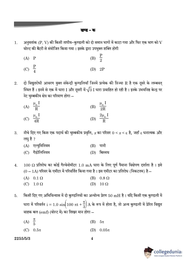
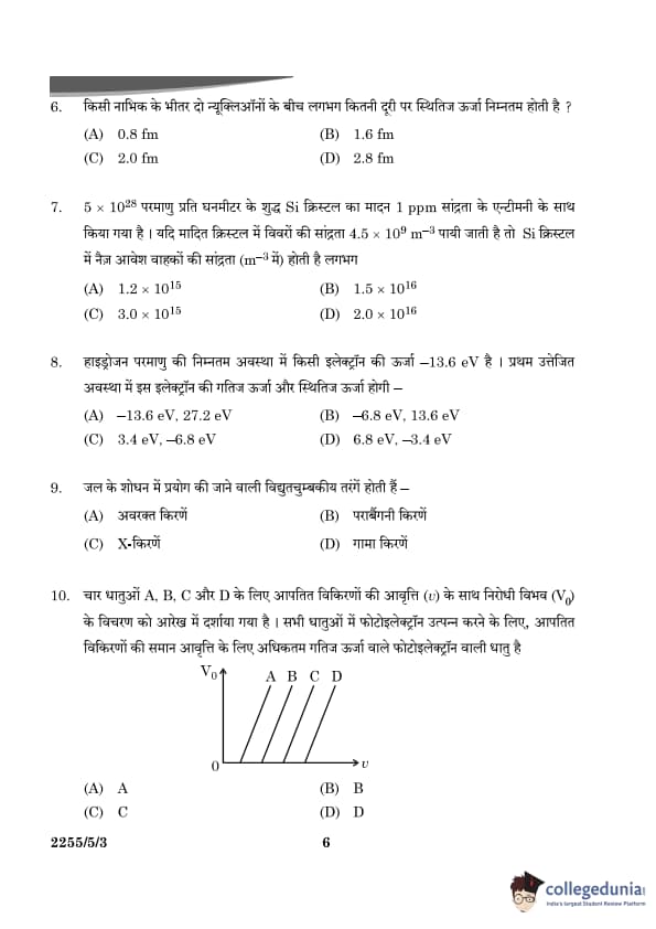
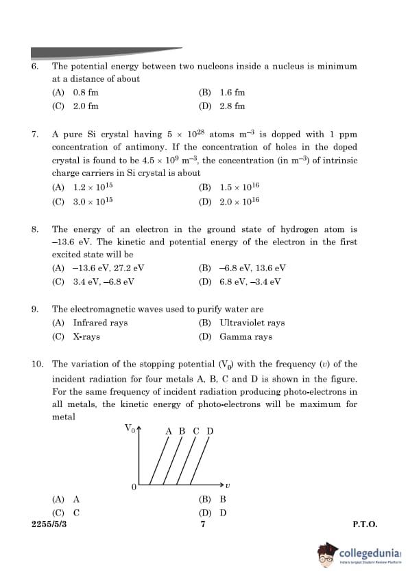
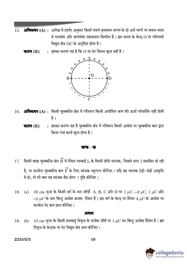
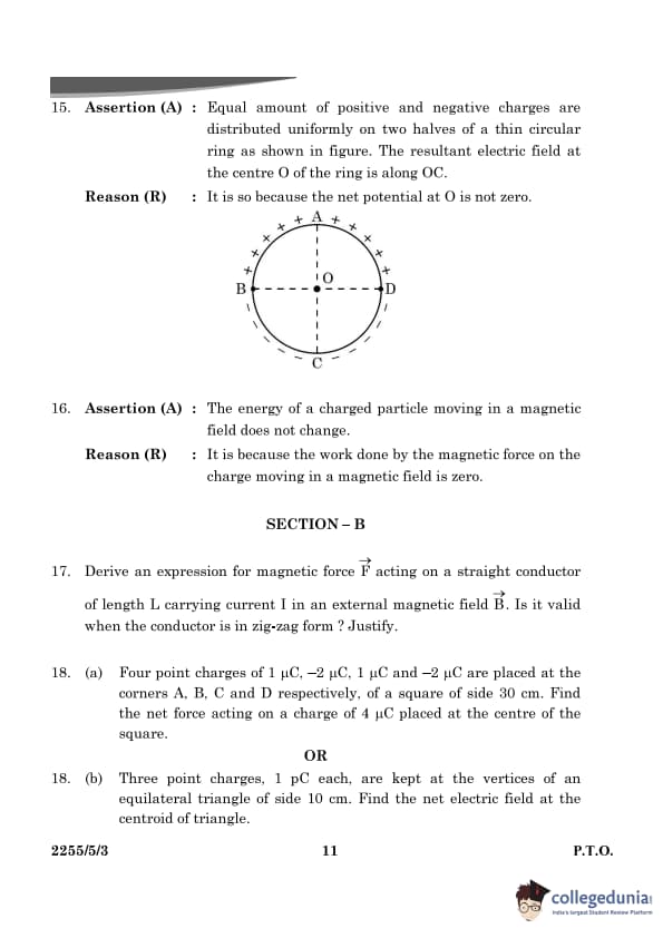
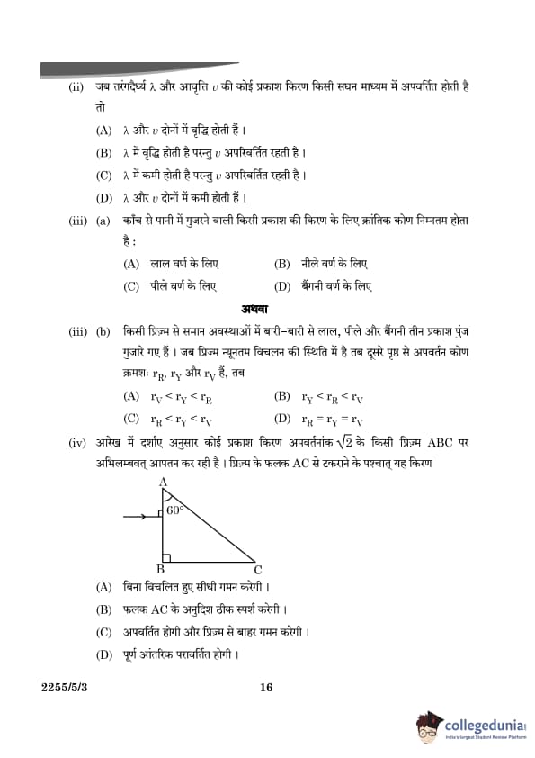
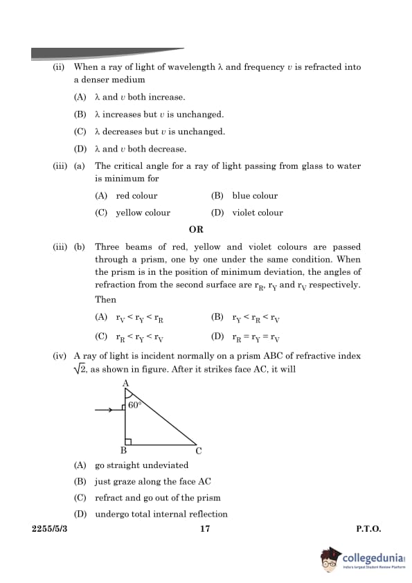


Comments